User Manual California Instruments
CSW Series 23
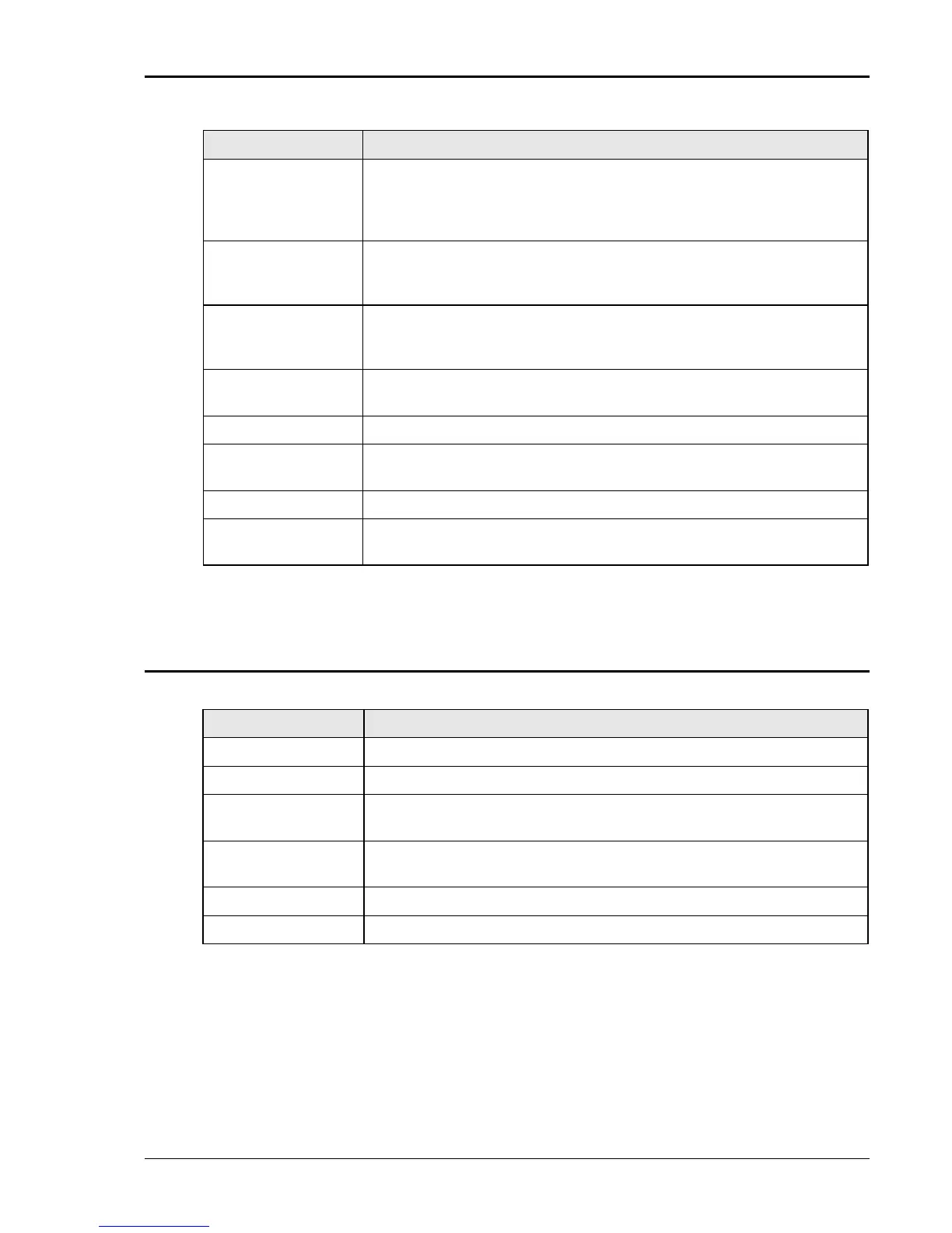
System Specification (continued)
Parameter Specification
Front Panel Trigger,
BNC connector
Output available at the front panel BNC connector that provides a
negative going pulse for any programmed voltage or frequency
change. The trigger can be reassigned as an output when running list
transients.
Front Panel Phase
A, B and C, BNC
connectors
These three outputs are representative of the programmed output
waveform, magnitude and frequency. 0 to 4.86 Vrms represents 0 to a
full-scale output voltage. The output impedance is 100 ohms.
External Signal Individual inputs for an external signal for each of the three phases. A 0
to 5.0 Vrms input provides a 0 to full-scale output voltage of the supplied
waveform
External Gain
Control (RPV)
Individual inputs for an external DC signal for each of the three phases. A
0 to ±7.07 VDC signal provides a 0 to full-scale output voltage.
/INHIBIT A logic Lo or contact closure input to inhibit the outputs
MOD An input for an amplitude modulation. 0 to 5 Vrms provides 0 to ≥20%
modulation for each of the three output phases
Trigger Input An input to trigger a function
External Synch A TTL input to frequency synchronize the outputs. The Phase A output
can be programmed relative to the external input.
2.1.6 Unit Protection
Parameter Specification
Input Overcurrent: Circuit breaker with current trip control.
Input Overvoltage: Automatic trip of input circuit breaker.
Input Overvoltage
Transients:
Surge protection to withstand EN50082-1 (IEC 801-4, 5) levels.
Output Overcurrent: Adjustable level constant current mode with a maximum set point
between 0% and 10% above programmed value.
Output Short Circuit: Peak and rms current limit.
Overtemperature: Automatic shutdown.

 Loading...

