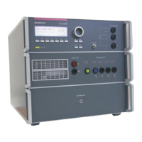
• The test generator and the coupling network should be connected directly to the reference ground plane.
• For the pulses 3a/3b the connection generator – groundplane shall not be longer than 100mm. The
connection shall be suitable for high frequencies.
• The DUT shall be isolated from the reference ground plane by 0.1m. This is also recommended for all
connected lines. The DUT should only be grounded if it is also recommended for the real installation in a
vehicle.
• Whenever possible the test set-up and the cabling should always be the same.
• The diodes or zeners are optional only for pulse 5b (suppressed)
• The load resistor Rv is optional. This resistor is used to match the generator to the low impedance battery
supply system. So far, as known, this is only used within the Ford ES-XW7T specification where Rv = 0.7
During the test the measuring circuit shall be removed from the test setup
The decoupling part of the coupling network has to:
- to decouple the pulses from the battery or the power
supply
- protect other systems that are connected to the same
power supply and realize a high impedance of the
power supply, e.g. battery supply.
 Loading...

