AMETEK CTS UCS 200N
Manual for Operation V 2.41 31 / 54
The coupling network
Via coupling network the pulses are injected to the lines of a vehicle battery supply system, according ISO 7637
as well as SAE J1113.
The coupling mode, capacitive coupling to the + line or via capacitive coupling clamp to signal lines, is selected
via the front panel keyboard of the UCS 200N or by ISO.control software.
The following options are available:
CAUTION!
Care must be taken that the inrush is not exceeded. Exceeding the inrush current limit, for any
amount of time, can result in damage to the equipment. Be sure to set the current limit on the
source accordingly. Using a battery is dangerous and not supported.
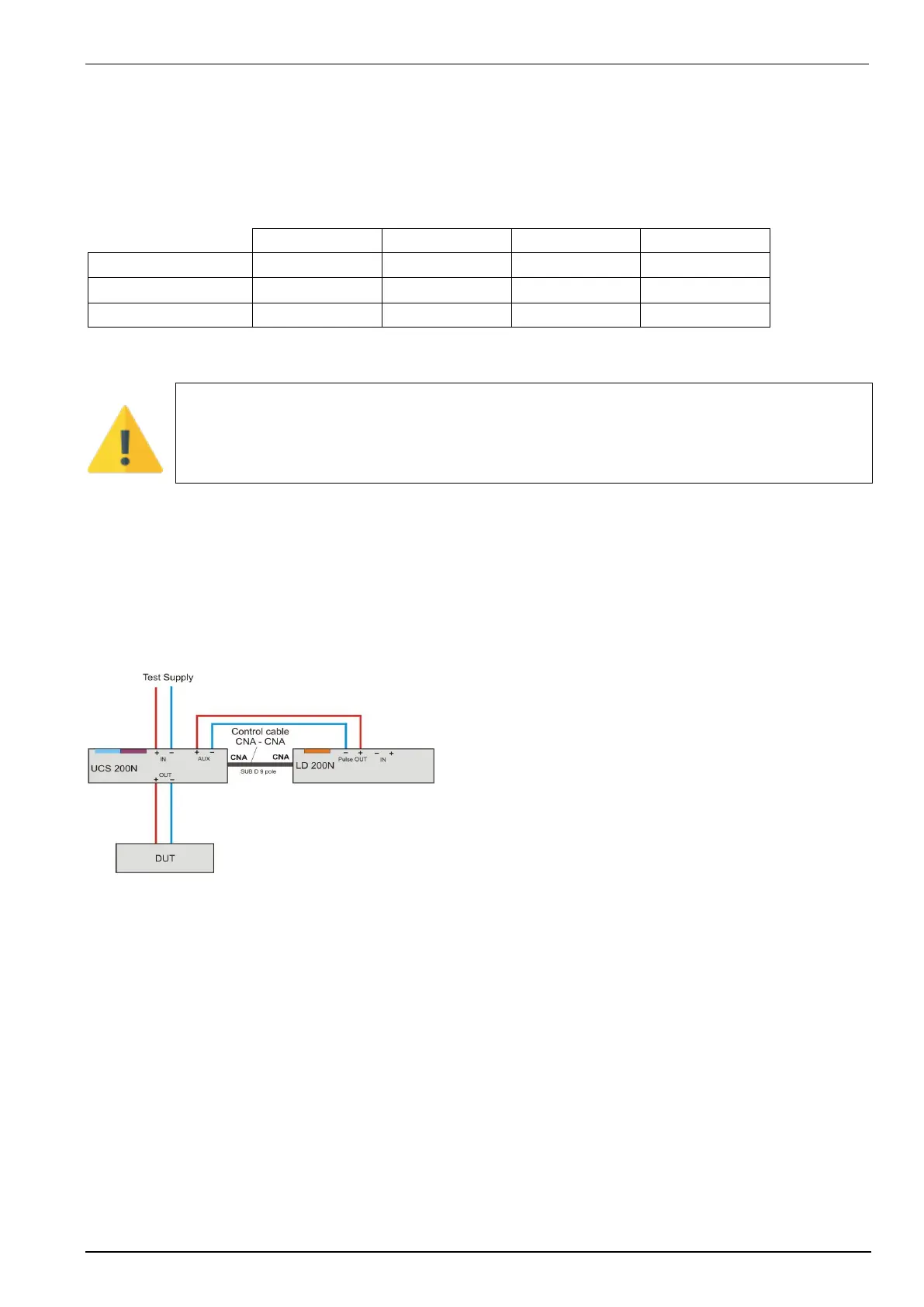
Installation:
The following connection between external generators (LD 200N) and coupling network (UCS 200Nx)
has to be made:
LD 200N
- Connect a 9-Pin SUB-D cable as a control line between LD
200N (CNA) UCS 200 (CNA).
- Connect the ± pulse out of the LD 200N to the ± Aux of the
UCS 200
- Connect the DUT to the output of the UCS 200.
- Select “F5 EXTERN” at the UCS *
* If you are using iso.control to remote control the generators,
this is be done by the software.
Control signals to UCS 200N :
polarity, trigger battery switch, interlock, pulse onto the + potential
 Loading...