AMETEK CTS UCS 200N
Manual for Operation V 2.41 32 / 54
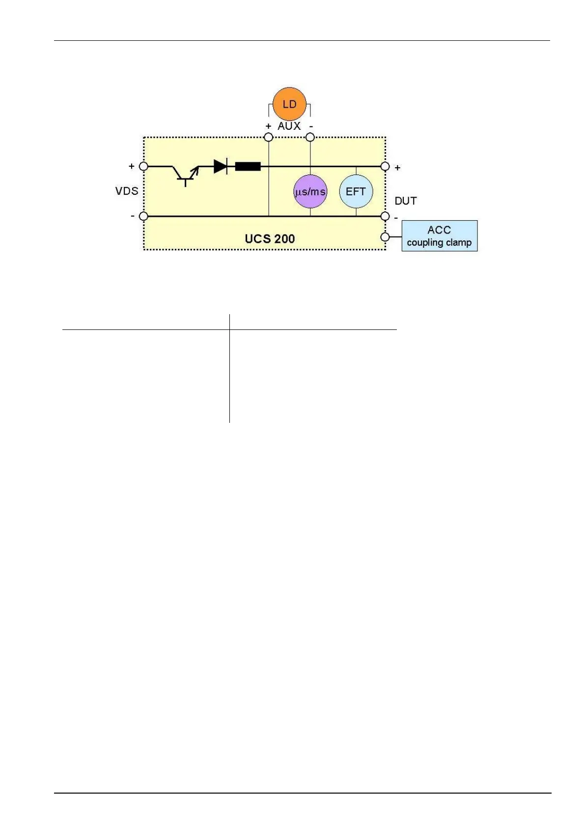
UCS 200N Coupling network general diagram
DC power supply +/- and pulse
Internal from UCS 200N module
Pulse A2, B2 and D2 (Jaso)
Internal from UCS 200N module
Internal from UCS 200N module
Pulse 5, 7 (ISO, Ford, Chrysler)
Pulse A1, B1 and D1 (Jaso)
+/- power supply lines for the DUT or DUT according ISO 7637 part 1
Coaxial output for connecting a capacitive coupling clamp according ISO 7637 part 3
Control functions
All functions of the coupling network are controlled via the keyboard of the pulse generators.
All test pulses are available at the central output of the UCS 200N.
Additionally the coupling network may also be controlled fully automatic via iso.control. All coupling modes and
test pulses are then controlled by the computer.
Before starting a test procedure the button TEST ON shall be pressed and the related LED is alighted.
Please take care that, within a fully automatic test setup which is supported by the iso.control software, all units of
the setup must be switched on. This is necessary to support all necessary communication between the
instruments.
 Loading...