AMETEK CTS UCS 200N
Manual for Operation V 2.41 54 / 54
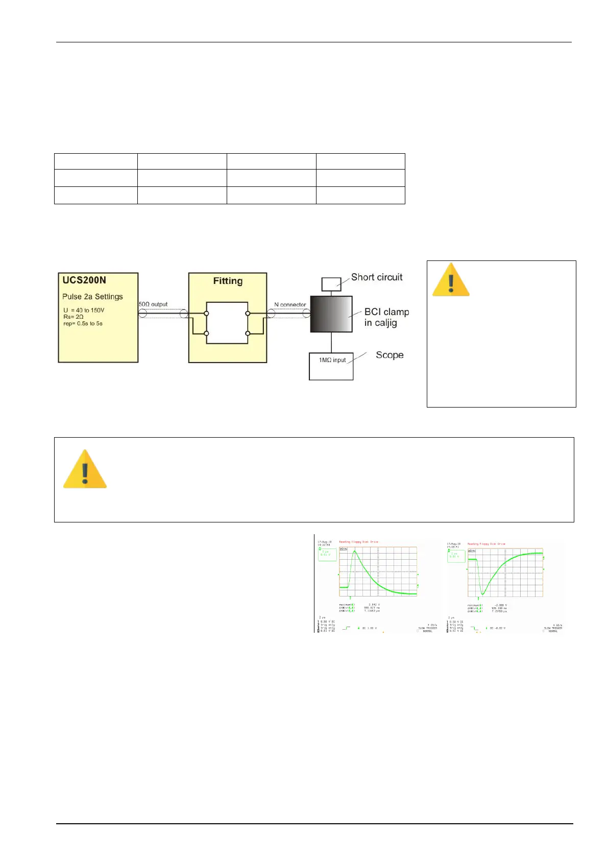
Setup for ICC testing as per ISO 7637-3
For testing as per ISO 7637-3 with the ICC clamp the standard recommends an output voltage of 3V to 10V.
These low voltages can not be realized direct with the UCS 200 generator.
A solution for get an ICC pulse is to use a matching network with an attenuator.
The ICC method specifies the test level as the output voltage measured with the calibration test setup. The
coupled pulse 2 in Quickstart mode shall fulfil the requirements of the table below.
Requirements for the coupled pulse as per ISO 7637-3 chapter 4.6
ICC SET ISO 7637 for ICC calibration and testing
Polarity
The polarity will change when:
- Change the CalJig
connectors
- Rotate the BCI 180
- Change polarity at the UCS
voltage.
The generator setting is according the standard. Important is the verification pulse at the BCI
output.
The MN-CIP9136 is equipped with typical values for the BCI clamp CIP 9136 model.
An exact fitting needs the original used BCI clamp mandatory.
Example of pulse measurement on Caljig output
BCI Clamp
tr = 0.88us
td = 7.2us
U = 2.98 V
The user is responsible to use this methode for ICC testing.
 Loading...