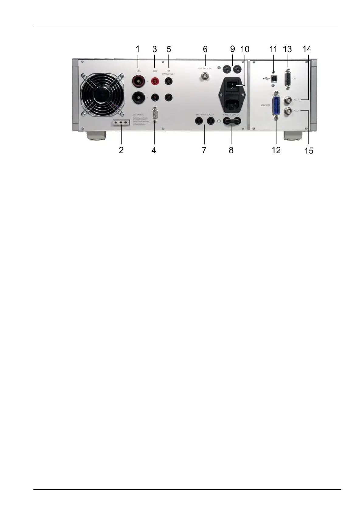
1 DUT test supply input
2 Reference earth connection
3 AUX Pulse input from ext. LD
4 Control input for ext. LD
5 Ext Impedance
1 DUT test supply input
The power supply for the DUT is connected to the safety laboratory connectors + and -. The front panel output is
decoupled by the internal coupling/ decoupling network.
2 Reference ground connection
The generator has to be connected to the reference ground plane of the test set up.
3 Pulse input for one external generator
The UCS 200N includes a central coupling matrix. The pulse output of an external Load Dump LD200 or
MPG 200 S20 generator can be connected to this input. The Load Dump pulses then will be available at the
central DUT output at the front panel of the UCS 200N
4 Control input for one external generator
The UCS 200N includes a central coupling matrix. The control output of the external generator can be
connected to this input. The external generator is able to control the UCS 200 coupling network.
5 External impedance
At this input an external resistor can be added to achieve impedance additional to those the generator includes.
Select the “External Rs” mode in the setup menu. The internal resistor automatically is set to 10 And the
external resistor is added.
6 External trigger
One single event, burst, surge, voltage dip or ESD can be released. Trigger level 5-15V positive going.
7 Warning lamp control
This relays contact (230V / 6A) can control warning lamps which may be installed in the test set-up (Test On).
8 Safety circuit
To connect an external security circuit.
9 Mains selector
Selection of 115V / 230V
10 Power on switch
The switch is part of the mains filter. Mains fuses are part of the filter. (230V / 1A and 115V / 2A)
 Loading...