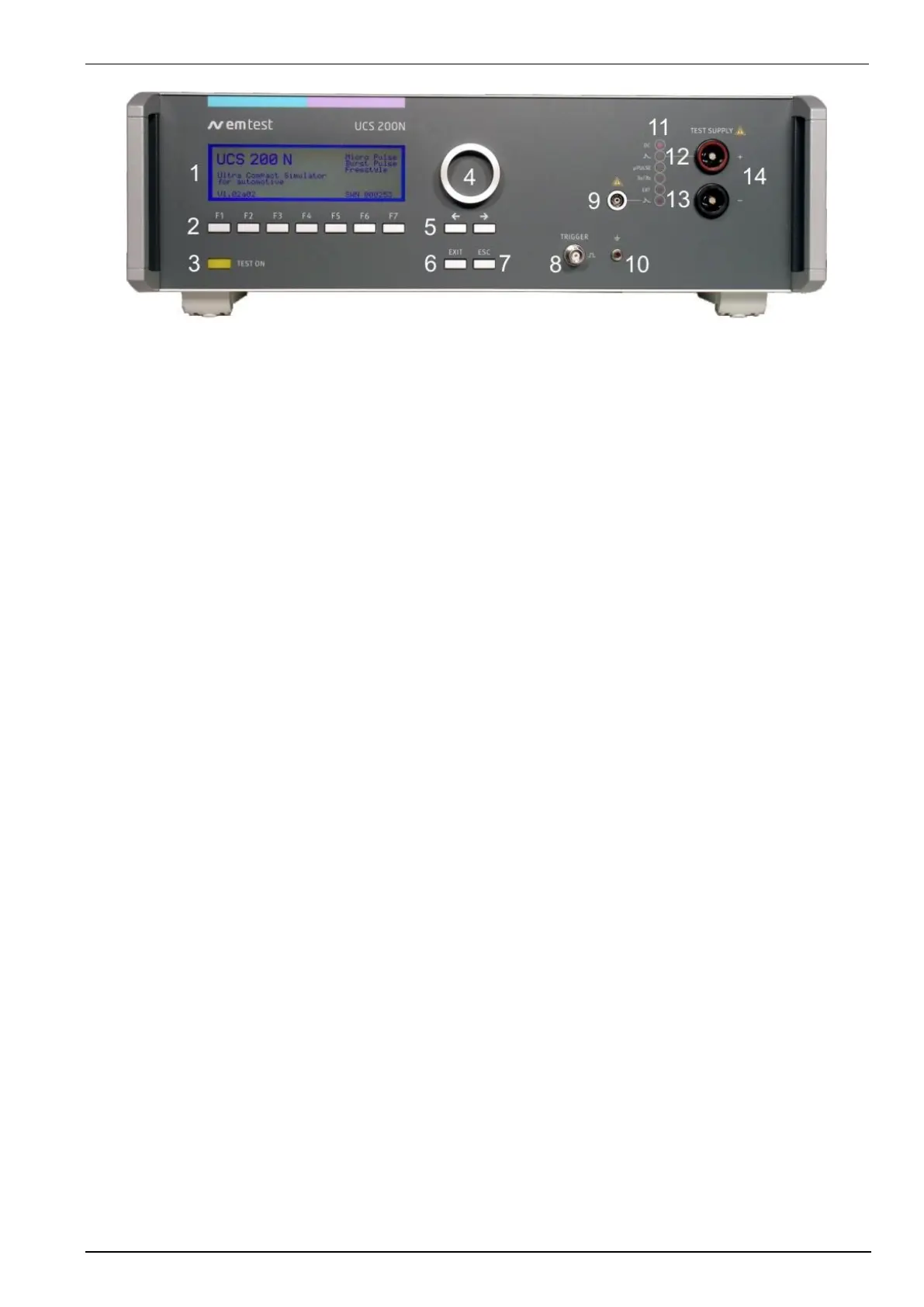
8 Oscilloscope trigger
9 HV pulse output 50 ohm
10 Earth plug for verification
11 LED: Indication battery switch
12 LED: Pulses available at + output
13 LED: Burst 3a/3b pulses
14 DUT test supply
11. Indication Battery Switch
The red LED shows whether the battery switch is off or on. For negative pulses the battery switch is switched
OFF / ON during pulse generation.
12. Red LED indication:
+ output, Micropulses, Burst 3a/3b pulses, External pulses,
The LEDs show the type of pulse and the output at which they are available.
13. Red LED indication:
The LEDs show the output on coaxial output for pulses 3a and 3b. This is the connection point for the
external coupling devices .
14. DUT test supply
The coupling / decoupling network is part of the generator. The DUT is powered via the safety laboratory plugs
at the front panel of the simulator. The nominal battery supply is 80V/50A. Higher currents, up to 200A, are
available on special request.
 Loading...