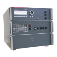
AMETEK CTS UCS 200N
Manual for Operation V 2.41 4 / 54
8.3.3. Calibration of Accessories made by passive components only ....................................................... 40
8.3.4. Periodically In-house verification ...................................................................................................... 40
8.4. Connectors to the DUT ..................................................................................................................... 41
9. Delivery .......................................................................................................................... 42
9.1. Basic accessory ................................................................................................................................ 42
9.2. Additional Accessories and options (separately available) .............................................................. 43
10. Appendix ........................................................................................................................ 45
10.1. Declaration of CE-Conformity ........................................................................................................... 45
10.1.1. UCS 200N50..................................................................................................................................... 45
10.1.2. UCS 200N100................................................................................................................................... 46
10.1.3. UCS 200N150................................................................................................................................... 47
10.1.4. UCS 200N200................................................................................................................................... 48
10.2. UCS 200N – internal Voltage drop ................................................................................................... 49
10.3. UCS 200N - General Diagram .......................................................................................................... 50
10.4. Main diagram control connection...................................................................................................... 51
10.5. Main diagram high voltage connection ............................................................................................. 53
10.6. Setup for ICC testing as per ISO 7637-3 .......................................................................................... 54
 Loading...

