Table of Contents
i
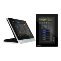
NXD-700i & NXT-CA7 7” Modero Touch Panels
Table of Contents
Modero 7" Touch Panels ....................................................................................1
Overview .................................................................................................................. 1
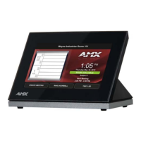
NXD-700i Overview .................................................................................................. 2
NXD-700i Specifications ................................................................................................. 2
NXD-700i Panel Connectors............................................................................................ 4
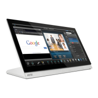
NXT-CA7 Overview................................................................................................... 4
NXT-CA7 Specifications ................................................................................................. 5
NXT-CA7 Panel Connectors............................................................................................. 6
NXD-700i - Installation .......................................................................................7
Overview .................................................................................................................. 7
Unpacking the Panel ................................................................................................. 7
Installing the No-Button Trim Ring ........................................................................... 7
Installing the Button Trim Ring ................................................................................. 8
Pre-Wall Installation of the Conduit Box ................................................................. 10
Installing the NXD-700i Touch Panel ...................................................................... 11
Installing the Panel Within a Conduit Box ..................................................................... 11
Installing the Panel Into Drywall Using Expansion Clips ................................................ 12
Installing the Panel Into a Flat Surface using #4 screws ................................................ 14
Installing the Panel into an (optional) Rack Mount Kit (NXA-RK7)................................. 15
Ethernet/RJ-45 Port: Connections and Wiring .............................................................. 16
NXT-CA7 - Installation ......................................................................................17
Overview ................................................................................................................ 17
Unpacking the Panel ............................................................................................... 17
Ethernet/RJ-45 Port: Connections and Wiring .............................................................. 17
PS-POE-AF PoE Injector ...................................................................................19
Overview ................................................................................................................ 19
Panel Calibration ..............................................................................................21
Overview ................................................................................................................ 21
Calibrating the Panel .............................................................................................. 21
Configuring Communication .............................................................................23
Overview ................................................................................................................ 23
Modero Setup and System Connection .................................................................. 23
Configuring and Using USB with a Virtual Master .................................................. 25
Step 1: Setup the Panel and PC for USB Communication ............................................. 25
Step 2: Confirm the Installation of the USB Driver on the PC ....................................... 25
Step 3: Confirm and View Current AMX USB Device Connections................................ 26

 Loading...