22 LCX 890 Installation Guide
Connecting the AC Power
Warning
Be sure the AC power cable is not connected to an electrical power
source while you are wiring the controller, or you could receive an
electrical shock that is life-threatening.
The AC power connection is to the right of the lower part of every LCX
890 series controller. You must wire the AC cable to the three screws
on that board.
Caution
Be sure to connect all three wires, HOT, NEUTRAL, and GROUND.
Otherwise, the controller could malfunction.
The three screws are labeled HOT NEU GND. The three wires at the
end of your AC cord are black, white, and green.
1. Place the green wire under the metal plate behind the top screw,
labeled GND.
2. Tighten the screw with a flathead screw driver.
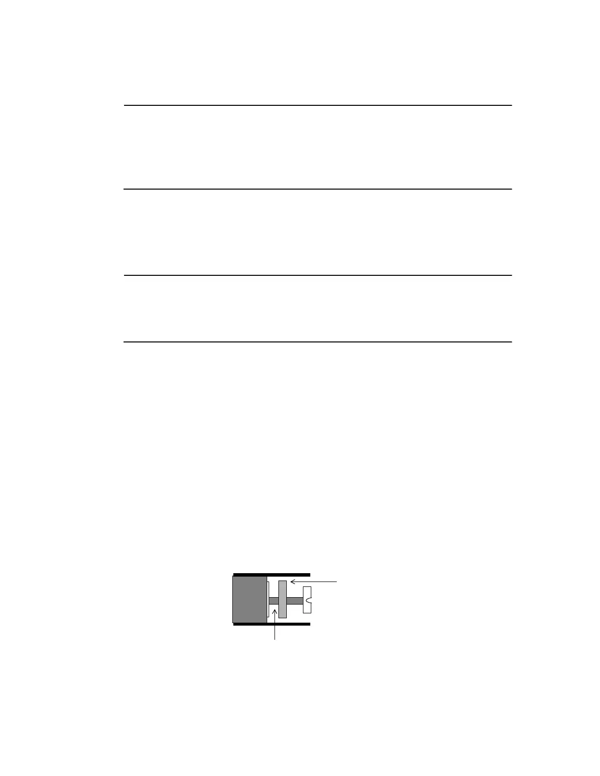
Figure 5 shows the position of the plate, where to place the wire, and
how the screw fits on the plate. You can see how the screw holds the
plate in place once you tighten it.
Figure 5. Metal Plate and Screw for Power Supply Wire
3. Place the white wire under the metal plate behind the middle screw,
labeled NEU.
Insert Wire Here
Metal Plate
 Loading...
