24 LCX 890 Installation Guide
2. Disconnect the jumper from E7 and connect it to E2, so it jumpers
E1 to E2.
3. Remove the jumper from E4 to E3.
Wiring the Infinet to the LCX 890/898
Note
You must use shielded cables for Infinet to ensure compliance with the
Class A FCC limits and to ensure reliable communications.
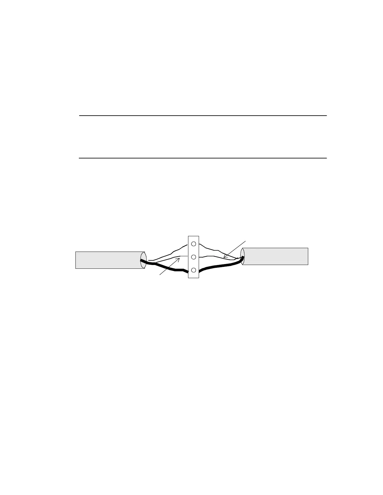
Figure 6 illustrates how to wire the Infinet cable to the removable block
terminal connector in the lower left corner of the LCX 890 or 898.
Figure 6. Infinet Cable Wiring
1. Trim back the shield over the wires.
2. Take the first wire for the incoming Infinet and the first wire for the
outgoing Infinet and slip both in the hole beneath the screw labeled
with a plus sign (top).
3. Tighten the screw down on them until the screw holds the wires in
place.
4. Slip the second (usually black) wire from each Infinet cable under
the screw labeled with a minus sign (middle) and tighten the screw
down on them.
5. Slip the shields from the incoming and outgoing Infinet cables under
the screw labeled SHLD (bottom) and tighten the screw down on
them.
+
–
SHLD
Infinet Connection
WHITE
WHITE
BLACK
BLACK
 Loading...
