LCX 890 Installation Guide 33
Follow these steps:
1. Loosen the screws for the first two inputs and their return terminal.
2. Slip the first wire for the first sensor under the input point screw for
input 1 and tighten the screw down on it.
3. Slip the first wire for the second sensor under the input point screw
for input 2 and tighten the screw down on it.
4. Slip the ground wires from both the first and second sensors under
the RETURN screw above input point 1 and tighten the screw down
on them.
5. Repeat the steps 1 through 3 for each pair of inputs.
Wiring a Thermistor Input
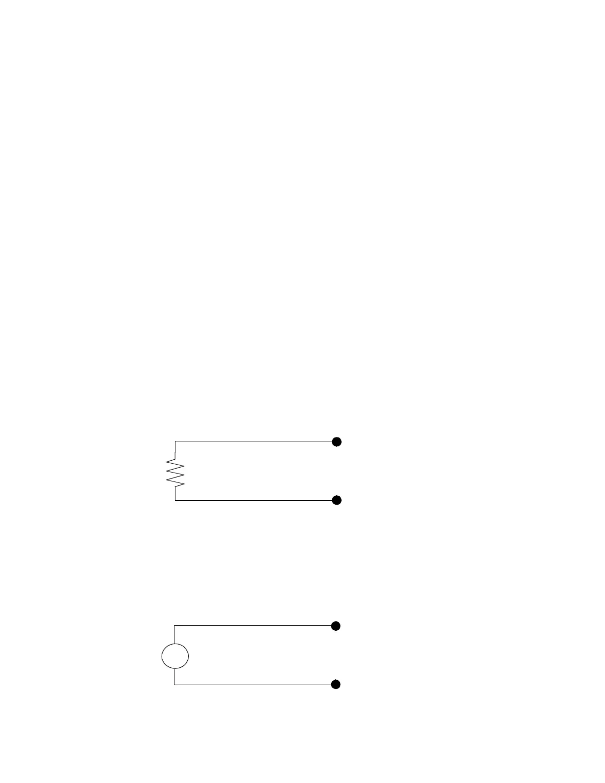
Figure 11 shows a thermistor attached to a universal input point. One
lead connects to the numbered input terminal, the other to a return
terminal.
Figure 11. Wiring Diagram for Thermistor Input
Wiring a Voltage Input
Figure 12 shows a voltage sensor wired to a universal input point.
Figure 12. Wiring Diagram for Voltage Input
1 (input point 1)
RET (return)
1 (input point 1)
RET (return)
V
+
–
 Loading...
