38 LCX 890 Installation Guide
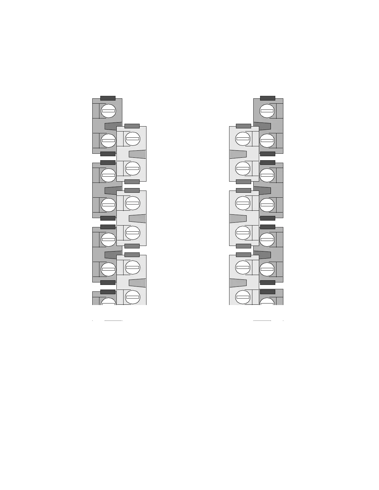
Figure 17 shows how the outputs on the LCX 898 are numbered.
Figure 17. Appearance, Positioning, and Numbering of Output
Relays on LCX 898
Wiring the Lights to the Output Relays
Wire the lights as follows:
1. Notice that each relay has two large screws on the top. Loosen the
screws.
2. Now look at the right side of a single output.
As shown in Figure 18, you see four small wire inlets, two under
each large screw.
Outputs
Numbered
from Top of
Cabinet Down
Output 25
Output 27
Output 29
Output 26
Output 28
Output 30
Output 2
Output 4
Output 6
Output1
Output 3
Output 5
 Loading...
