44 LCX 890 Installation Guide
Wiring Three-Wire Momentary Switch
with No Status Feedback
Adjacent to each output are four terminal screws that you can wire a
momentary switch to. If you are wiring a three-wire device (one that
does not give status feedback), you wire it with up to 1,600 ft (487.7 m)
of 20/4 AWG (0.5 mm
2
/4) wire, as follows:
1. Loosen the BLK, RED, and WHT screws.
2. Slip the black wire under the BLK screw and tighten the screw down
on it.
3. Slip the red wire under the RED screw and tighten the screw down
on it.
4. Slip the white wire (or other alternate color) under the WHT screw
and tighten the screw down on it.
5. Ignore the last screw.
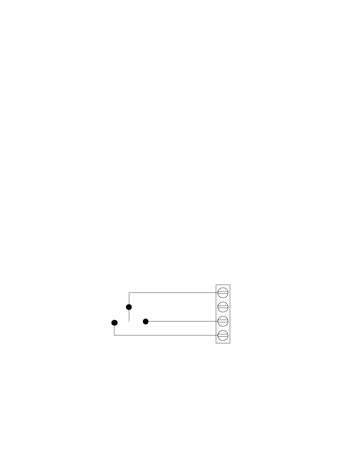
Figure 4 shows a wiring diagram for a three-wire momentary switch.
Figure 22. Wiring Diagram for Three-Wire Momentary
Switch
You can wire a daylight photosensor the same way, but you can use up
to 500 ft (152.4 m) of 20/3 AWG (0.5 mm
2
/3) RSWIRE-3 or RSWIRE-
3P.
RED (ON)
WHT
BLK (OFF)
YEL
 Loading...
