50 LCX 890 Installation Guide
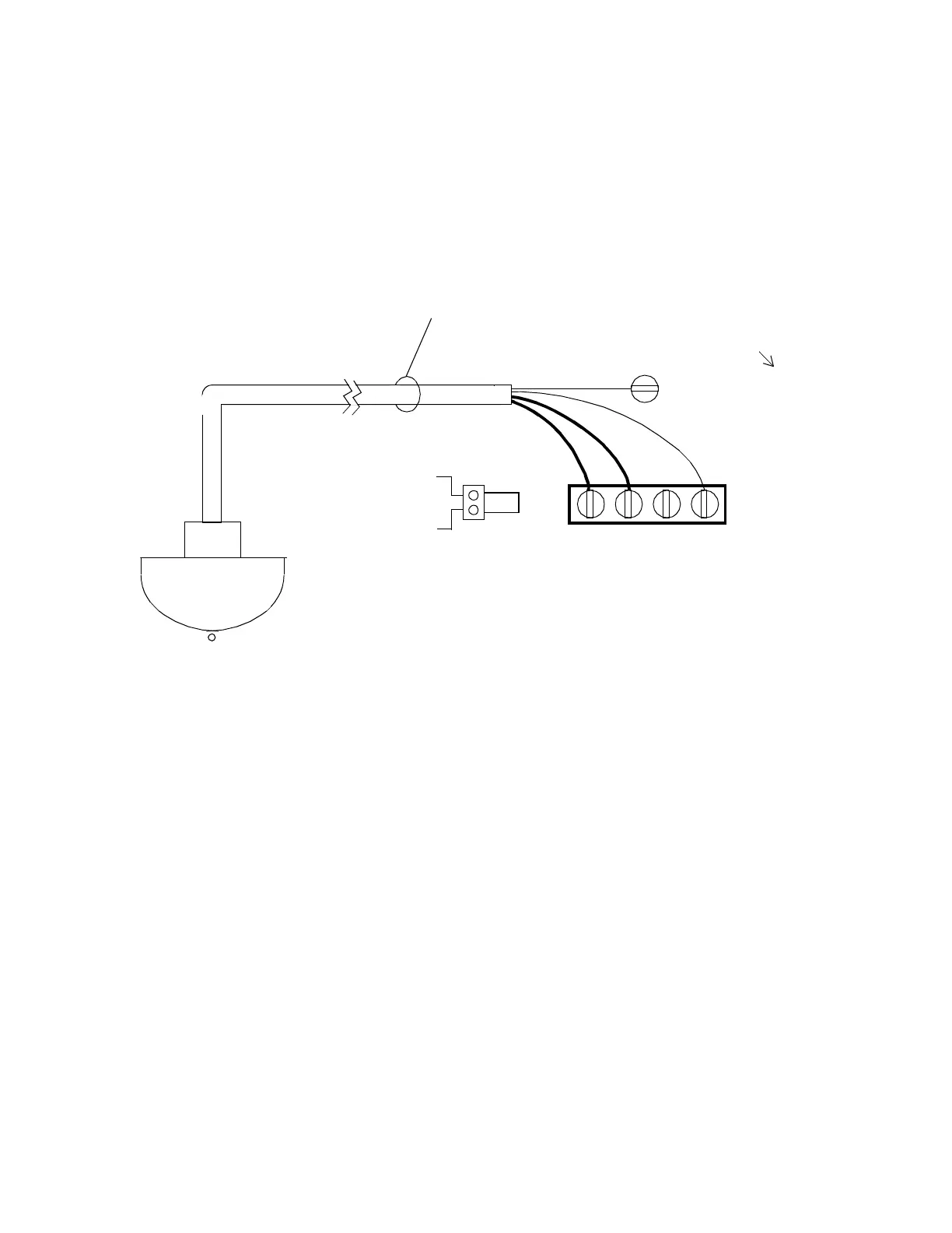
Figure 8 shows a wiring diagram for an occupancy sensor (motion
detector). You may choose to connect the white wire to the WHT screw
near the BLUE one for convenience rather than wiring the white wire
to the WHT terminal on the momentary override terminal block.
Figure 26. Wiring Diagram for Occupancy Sensor
Wiring an Occupancy Sensor
as a Momentary Override for Two Outputs
Figure 9 shows a wiring diagram for an occupancy sensor (motion
detector) to control two adjacent outputs. This way you can have one
occupancy sensor for the two areas. You can use up to 500 ft (152.4 m)
of 20/4 AWG (0.5 mm
2
/4)wire.
One occupancy sensor can control a maximum of two outputs. You can
have up to two momentary switches/occupancy sensors (four outputs)
wired this way on the entire controller.
BLK YELRED WHT
BLUE (+24 VAC Rect.)
(ON) (OFF)
. . .
V
1st Output
# 20/6
1000ft Maximum
ROSWIRE-6
ROSWIRE-6P
(Refer to earlier illustration
for location on controller.)
 Loading...
