LCX 890 Installation Guide 25
Wiring the Infinet to the 9000 Controller
You connect the last piece of Infinet cabling to the 9000 controller, as
described below (refer to the illustration):
1. Open the front of the 9000 controller cabinet.
Notice that to the left are three ports labeled COMM1, COMM2, and
COMM3. Two RS-485 ports, one above the three comm ports and
one below, are in the same area.
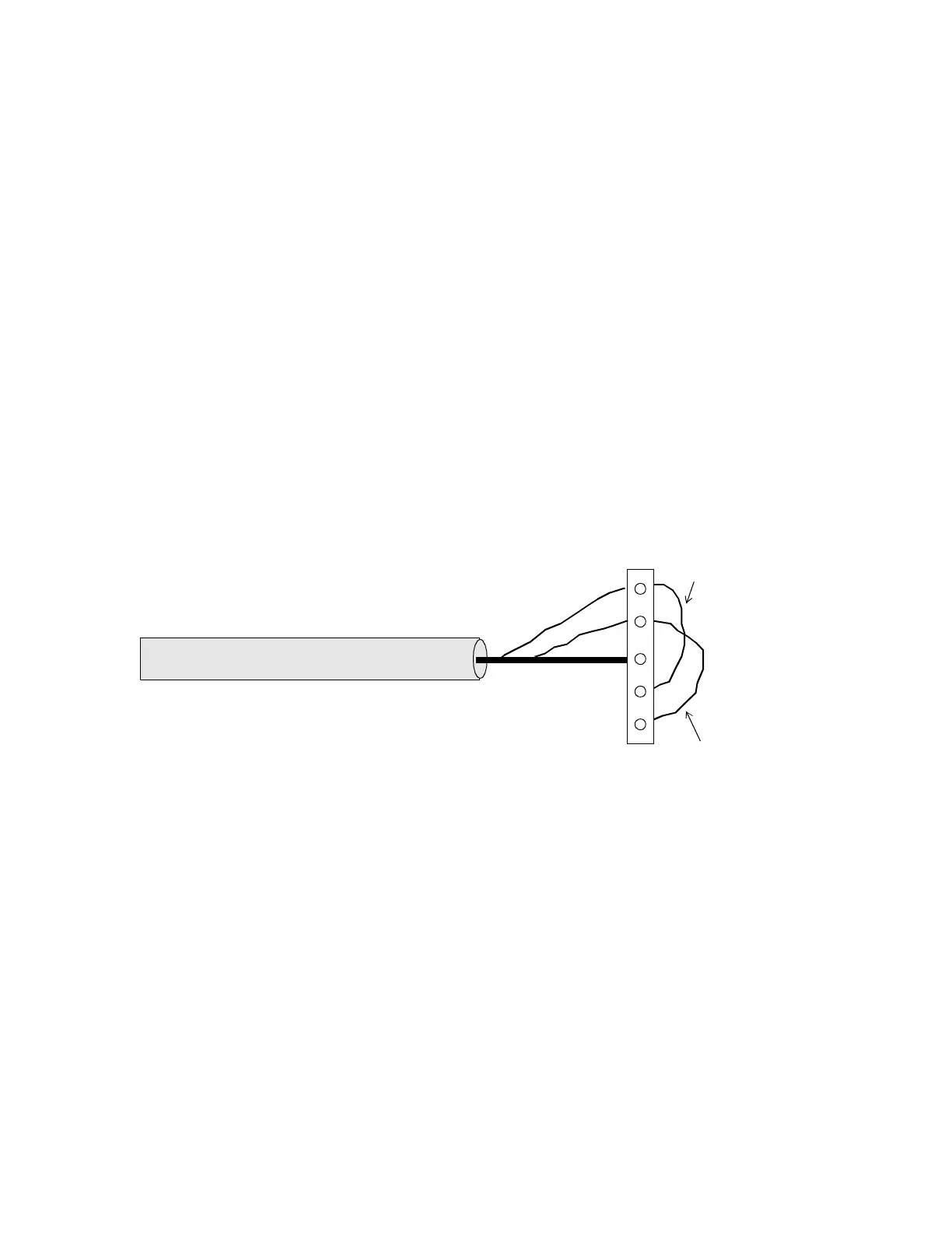
Notice that the end of the Infinet cable has two wires and a shield.
You wire them to the terminal block connector on the RS-485 port.
Figure 7 illustrates how to wire the Infinet cable to the 9000
controller.
Figure 7. Attaching the Infinet Cable to the 9000 Controller
2. Run the cable through the knockout on the left side of the controller.
3. Select the port to wire the cable to—either the RS-485 port just
above the three RS-232 ports (COMM2) or the RS-485 port just
below the three RS-232 ports (COMM1). Once you use either of
these ports for COMM1 or COMM2, the RS-232 port for COMM1
or COMM2 is disabled.
4. Trim back the shield over the wires.
5. Slip the first wire through the hole under the screw labeled +IN and
jumper it to the screw labeled +OUT.
+OUT
–OUT
SHLD
+IN
–IN
WHITE
BLACK
 Loading...
