EasyManuals Logo

Andover Controls LCX 890 Series User Manual

Default Icon
71 pages
To Next Page IconTo Next Page
To Previous Page IconTo Previous Page
Page #46 background imageLoading...
Page #46 background image
36 LCX 890 Installation Guide
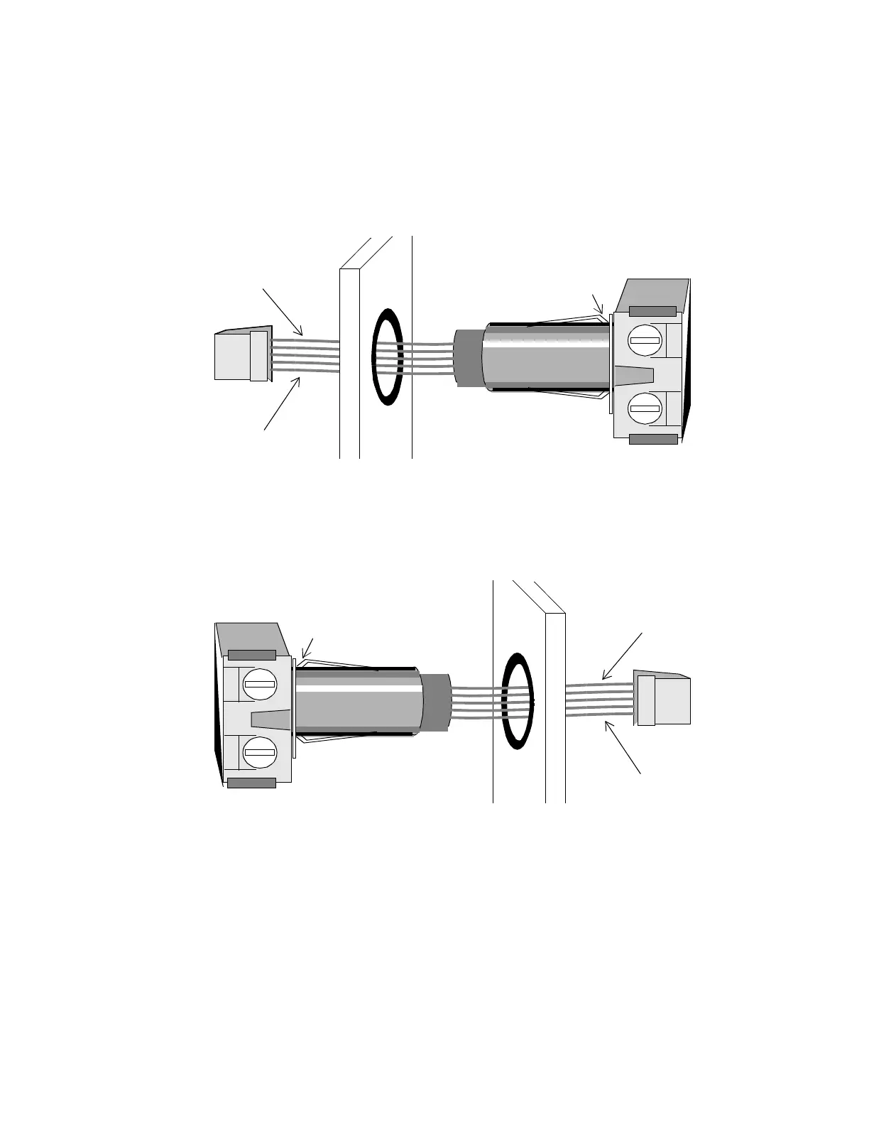
Figure 14 shows how to insert the relay on the LCX 890 or the right side
of the LCX 898.
Figure 14. Inserting a Relay for an Output on LCX 890 or
Right Side of LCX 898
Figure 15 shows how to insert the relay on the left side of the LCX 898.
Figure 15. Inserting a Relay for an Output on the Left Side of
the LCX 898
To remove a relay, grasp the square end of the relay and gently pull up-
ward and out to release the lower latch.
This Is Where Relay
Latches to Divider
Blue
Yellow
This Is Where Relay
Latches to Divider
Blue
Yellow

Table of Contents

Questions and Answers:

Question and Answer IconNeed help?

Do you have a question about the Andover Controls LCX 890 Series and is the answer not in the manual?

Andover Controls LCX 890 Series Specifications

General IconGeneral
BrandAndover Controls
ModelLCX 890 Series
CategoryController
LanguageEnglish

Related product manuals