LCX 890 Installation Guide 43
Wiring Four-Wire Momentary Switch
with Status Feedback
Adjacent to each output are four terminal screws that you can wire a
momentary switch to. If you are wiring a four-wire device (one that
gives status feedback), you wire it with up to 1,600 ft (487.7 m) of 20/4
AWG RSWIRE-3 (0.5 mm
2
/4) (standard class) or RSWIRE-3P (for
plenum applications), as follows:
1. Loosen the four screws you are connecting the input wires to.
2. Slip the black wire under the BLK screw and tighten the screw down
on it.
3. Slip the red wire under the RED screw and tighten the screw down
on it.
4. Slip the white wire under the WHT screw and tighten the screw
down on it.
5. Slip the yellow wire under the YEL screw and tighten the screw
down on it.
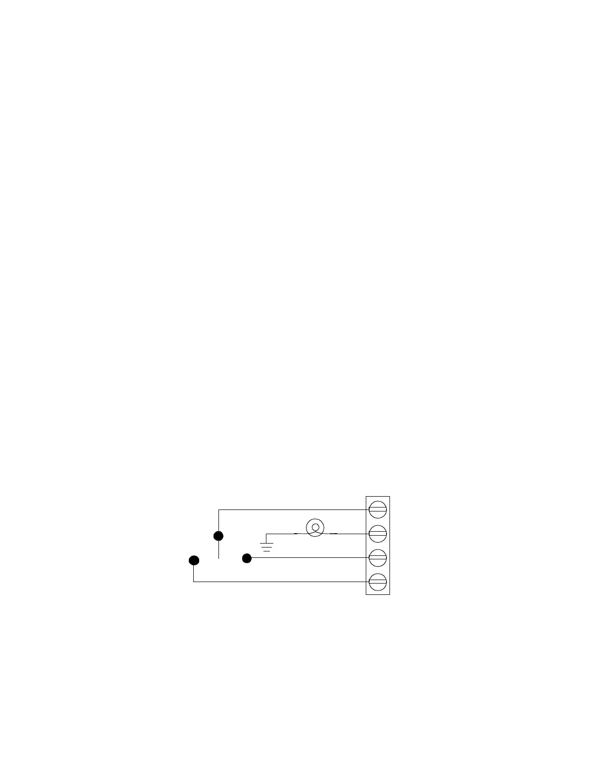
Figure 3 shows a wiring diagram for a four-wire momentary switch.
Figure 21. Wiring Diagram for Four-Wire Momentary Switch
RED (ON)
WHT
BLK (OFF)
YEL
 Loading...
