LCX 890 Installation Guide 47
Wiring a Single Momentary Switch
to Multiple Adjacent Outputs on LCX 898
On an LCX 898 controller you can wire a single momentary switch to
two, three, or four adjacent outputs. Follow the directions for wiring a
single momentary switch to two adjacent outputs to wire the third and
fourth output.
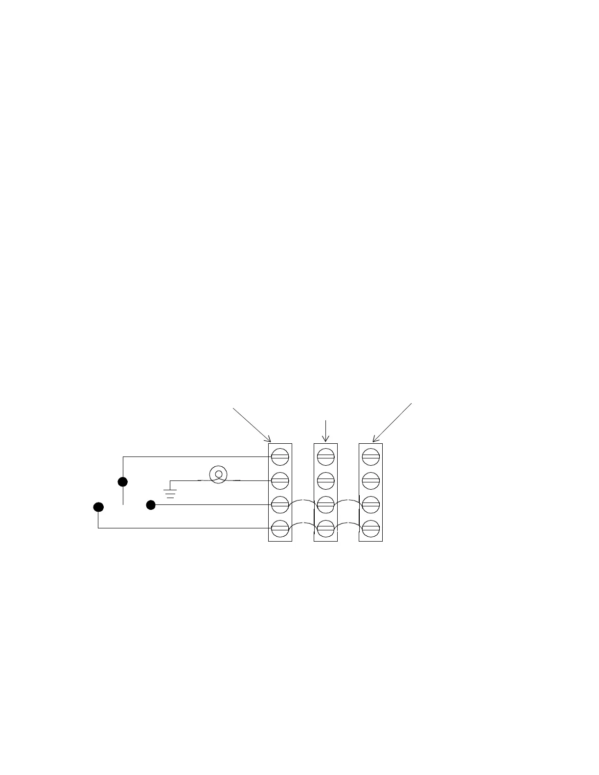
Figure 6 shows a wiring diagram for a four-wire momentary switch to
control three adjacent outputs. This way you can have a “master” switch
for the three areas.
Since one momentary switch can control a maximum of four outputs,
you can have up to two momentary switches/occupancy sensors (eight
outputs) wired this way on the entire controller.
Figure 24. Wiring Diagram for Four-Wire Momentary Switch
Controlling Three Adjacent Outputs (LCX 898 Only)
RED (ON)
WHT
BLK (OFF)
YEL
First
Output Terminal
Second Adjacent
Output Terminal
Block Block
Third Adjacent
Output Terminal
Block
 Loading...
