46 LCX 890 Installation Guide
10. If the device does not provide feedback, skip this step. If the device
does provide feedback, slip the yellow wire under the YEL screw
and tighten the screw down on it.
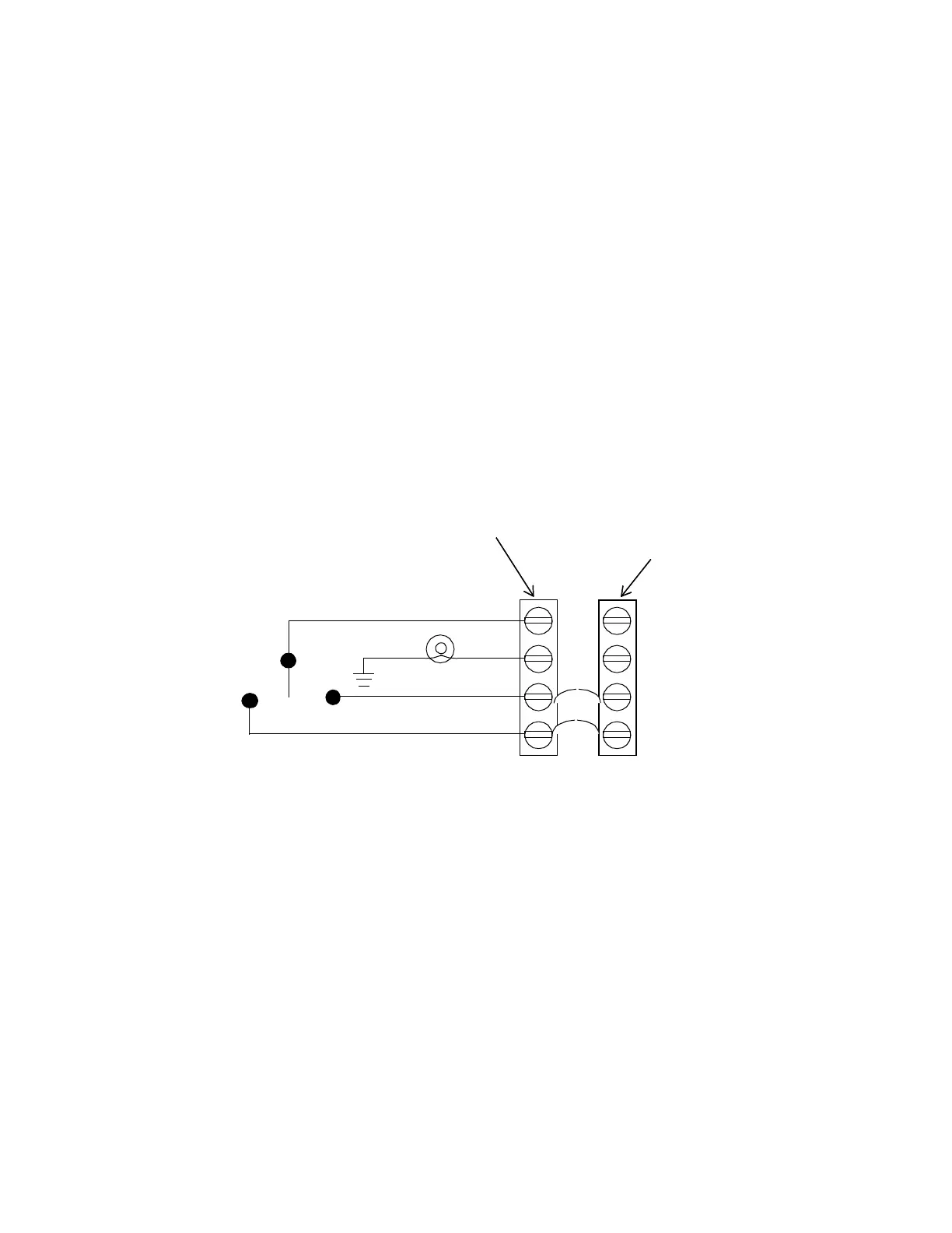
Figure 5 shows a wiring diagram for a four-wire momentary switch to
control two adjacent outputs. This way you can have a “master” switch
for the two areas.
Since one momentary switch can control a maximum of two outputs,
you can have up to two momentary switches/occupancy sensors (four
outputs) wired this way on the entire controller.
Figure 23. Wiring Diagram for Four-Wire Momentary Switch
Controlling Two Adjacent Outputs
First
Output Terminal
Next Adjacent
Output Terminal
Block
Block
RED (ON)
WHT
BLK (OFF)
YEL
 Loading...
