34 LCX 890 Installation Guide
Wiring a Current Input
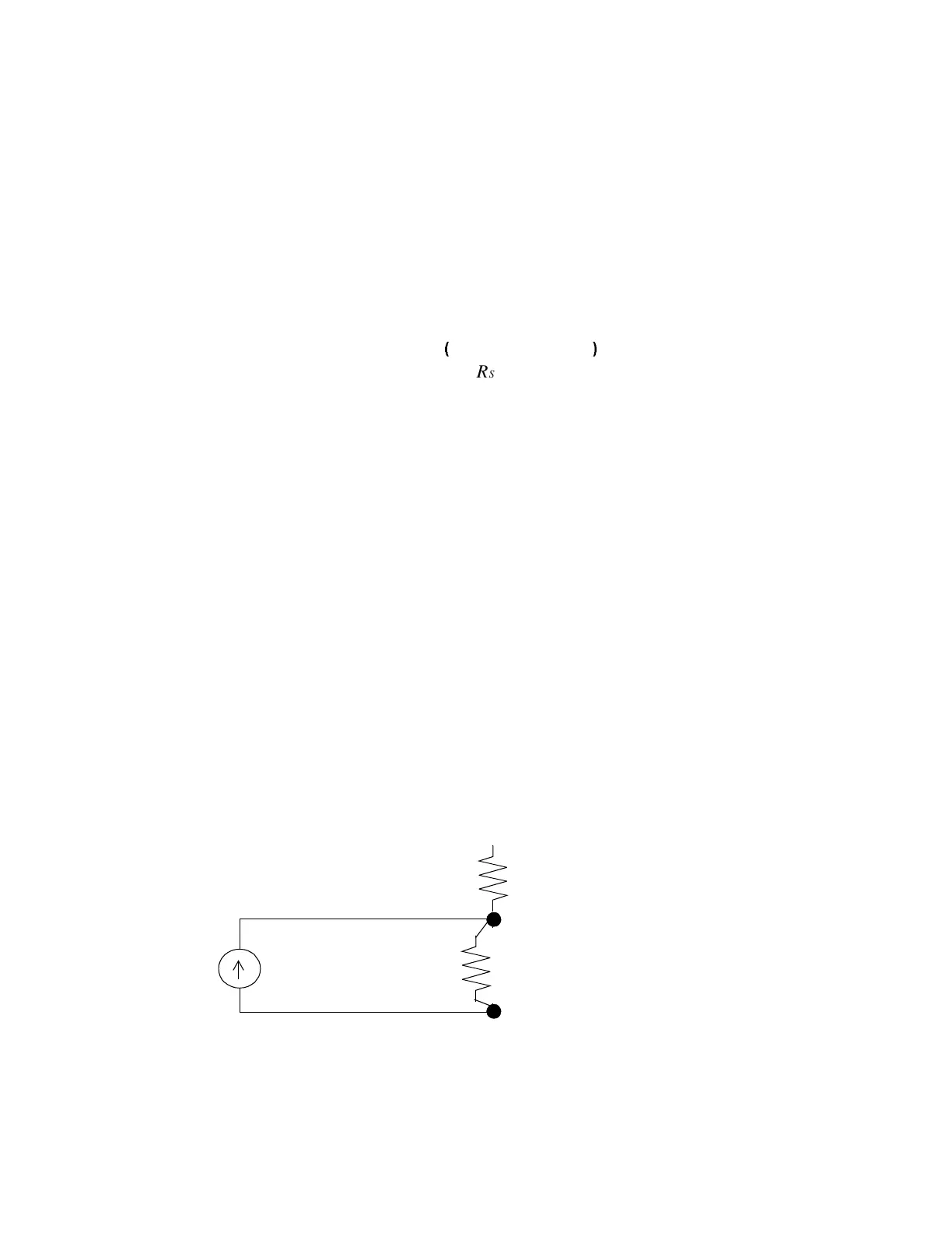
Figure 13 shows a current sensor wired to a universal input point. You
must wire a resistor across the input.
The exact number of Ohms resistance required varies based on the range
of current—while we recommend 249Ω for a 0 to 20 mA input, you can
also calculate the appropriate resistance with the following formula:
To account for the input current rising slightly above the maximum
(such as slightly over 20 mA), you should choose a value slightly below
the maximum resistance that solves the equation. The V
IN
should not ex-
ceed 5.115 V.
You then select the next standard resistor with a 0.1% or 1% tolerance.
(The accuracy of the input is directly proportional to the tolerance of the
resistor. So the lower the tolerance, the greater the accuracy.) The watt-
age rating should be greater than or equal to watt. Be sure you check
the Infinity Controller Programmer’s Guide or the ICS Controller Pro-
grammer’s Guide for details on how to convert the voltage from a
current input to other units.
Figure 13. Wiring Diagram for Current Input
V
IN
R
S
10
KI
max
5.120+×
R
S
10K+
---------------------------------------------------------=
4
---
1 (input point 1)
RET (return)
R
Sensor
= 249
Ω
with wattage
rating
1
4
---
Watt
≥
R
Pullup
= 10K
V
Ref
= 5.120
 Loading...
