LCX 890 Installation Guide 23
4. Tighten the screw with a flathead screw driver.
5. Place the black wire under the metal plate behind the bottom screw,
labeled HOT.
6. Tighten the screw with a flathead screw driver.
7. Do not close the AC power connection until you have completed the
installation.
Selecting the AC Input Voltage
The voltage of every LCX 890 series controller is set to 115 V when
shipped. To change the voltage, you must reset the jumpers to the right
of the AC power cord connection.
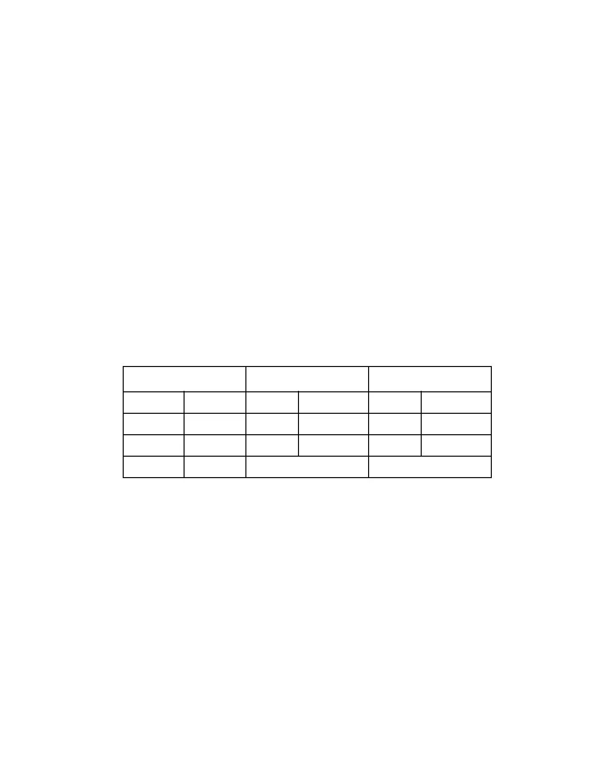
Table 7 shows jumper settings for the three voltages.
Table 7. Connecting Jumpers for AC Input Voltages
To change the voltage from 115 V to 230 V, proceed as follows:
1. Disconnect the jumper end from E5 and move it to E6 so it jumpers
E6 to E8.
2. Leave the other jumper as it is.
3. Remove the jumper end from E4 to E3.
To change the voltage from 115 V to 277 V, proceed as follows:
1. Disconnect the jumper end from E5 and move it to E6 so it jumpers
E6 to E8.
115 Jumpers 230 V Jumpers 277 V Jumpers
From To From To From To
E5 E8 E6 E8 E6 E8
E1 E7 E1 E7 E1 E2
E4 E3 Remove 3rd Jumper Remove 3rd Jumper
 Loading...
