LCX 890 Installation Guide 51
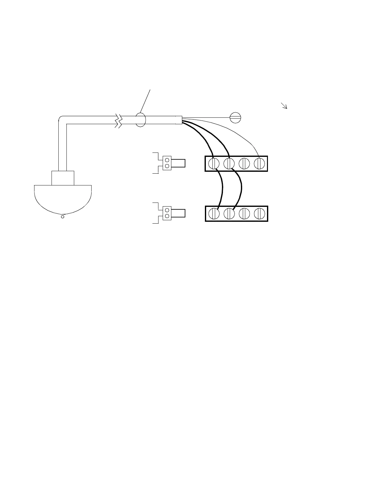
Figure 27. Wiring Diagram for Occupancy Sensor
Controlling Two Adjacent Output
Wiring an Occupancy Sensor
to Set Lighting to ON/OFF or HI/LO
Figure 10 shows a wiring diagram for an occupancy sensor (motion
detector) to control two separate adjacent outputs. The first output
controls the first two fluorescent tubes and the second the remaining
fluorescent tubes. You ground it only once and connect the blue wire to
the +24 VAC RECT terminal block.
You can use up to 1,000 ft. (304.8 m) of 20/6 AWG (0.5 mm
2
/6)
ROSWIRE-6 or ROSWIRE-6P.
BLK YELRED WHT
(ON) (OFF)
BLK YELRED WHT
BLUE (+24 VAC Rect.)
(ON) (OFF)
. . .
. . .
V
1st Output
2nd Output
# 20/6
1000ft Maximum
ROSWIRE-6
ROSWIRE-6P
(Refer to earlier illustration
for location on controller.)
V
 Loading...
