32 LCX 890 Installation Guide
Caution
Follow the rules below when wiring inputs and outputs:
• Never lay wires across the surface of the printed circuit board. You
should bring input wires in from the left and output wires in from the
right.
• Bundle excess wires toward the back of the cabinet to avoid any
contact with circuit boards.
• Wires should never be within 1 in. (25 mm) of any component on the
printed circuit board.
• Keep cabinet free of foreign materials (extra power supplies, relays,
and so on).
• Be careful when stripping wire not to drop small pieces of wire
inside the cabinet.
If you violate any of these rules, the controller could malfunction.
Wiring a Switch Input
Notice that the group of switch inputs are labeled IN1, RET, IN2, then
IN3, RET, IN4, and so on. The return terminal goes to the two inputs on
either side of it.
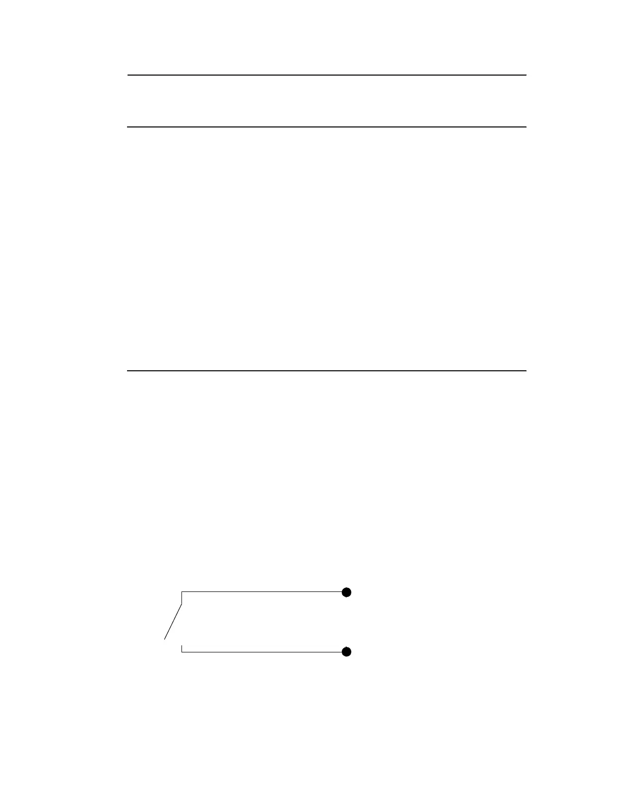
Figure 10 shows a switch wired to an input point. You follow this
diagram when wiring the first 16 inputs on the LCX 890. You may not
wire anything other than a switch to these 16 inputs.
Figure 10. Wiring Diagram for a Digital (Switch) Input
1 (input point 1)
RET (return)
 Loading...
