Chapter 1 — General Information 1-3 Remote Operation Setup and Interface
S331L PM PN: 10580-00322 Rev. F 1-5
Connectivity
TCP/IP connectivity requires setting up the parameters that are described at the beginning of
this section. The following is a brief overview of how to set up a general LAN connection on
the Site Master.
Site Master LAN Connections
The S331L requires the use of an external USB-Ethernet dongle, such as Anritsu part
number 2000-1810-R, to connect the Site Master to a local area network (LAN). Integrated
into this dongle are two LEDs (Light Emitting Diodes). The amber LED indicates the speed of
the LAN connection (ON for 100 Mb/s and OFF for 10 Mb/s), and the green LED flashes to
show that LAN traffic is present. The instrument IP address is set automatically by using
Dynamic Host Configuration Protocol (DHCP). DHCP is an Internet protocol that automates
the process of setting IP addresses for devices that use TCP/IP, and is the most common
method of configuring a device for network use. After the Ethernet cable is connected to the
instrument, go to System, Status, Connectivity Info to view the IP address that the
instrument has been assigned.
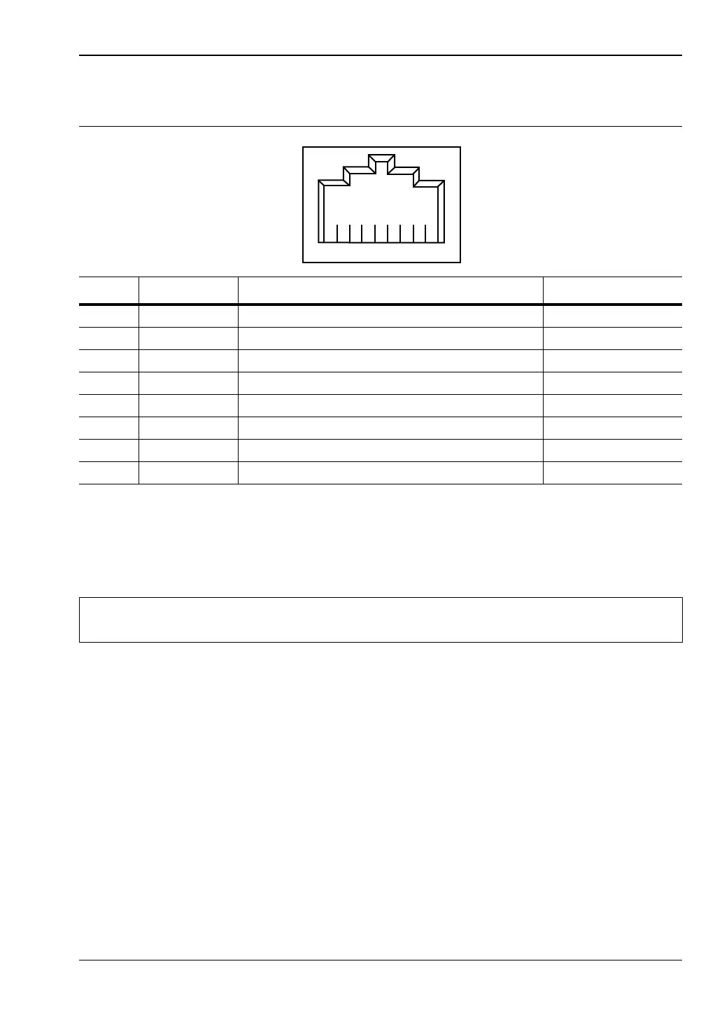
Table 1-1. 8-pin Ethernet RJ45 Connector Pinout Diagram
Pin Name Description Wire Color
1 TX+ Transmit data (> +3 volts) White/Orange
2 TX– Transmit data (< –3 volts) Orange
3 RX+ Receive data (> +3 volts) White/Green
4 — Not used (common mode termination) Blue
5 — Not used (common mode termination) White/Blue
6 RX– Receive data (< –3 volts) Green
7 — Not used (common mode termination) White/Brown
8 — Not used (common mode termination) Brown
Note
You may need to consult your network documentation or network administrator for
assistance in configuring your network setup.

 Loading...


