5-2 Procedure CW Signal Generator (Option 28)
5-2 PN: 10580-00349 Rev. H Spectrum Analyzer MG
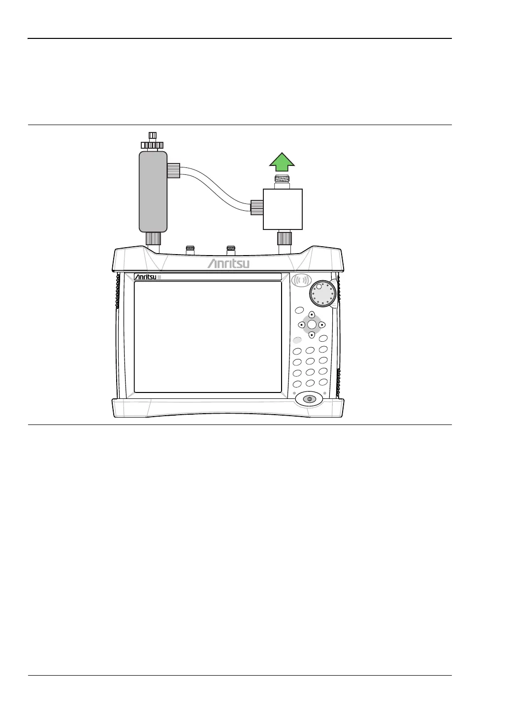
5-2 Procedure
1. On the instrument, press the Menu key and select the CW Signal Generator icon.
2. Connect the attenuator to the RF Out port and the splitter to the Spectrum Analyzer
RF In port as show in Figure 5-1.
Figure 5-1. CW Signal Generator Configuration
Power Charge
+/-
.
0
3
Sweep
2
Calibrate
1
Preset
6
Limit
5
Trace
4
Measure
9
Mode
8
System
7
File
Shift
Esc
Enter
Menu
RF Out
Adjustable
Attenuator
Spectrum Analyzer
RF In
Output
Splitter
ООО "Техэнком" Контрольно-измерительные приборы и оборудование www.tehencom.com
 Loading...


