General Maintenance and Troubleshooting
SM 6495, Rev. 7, December 2008 2-5
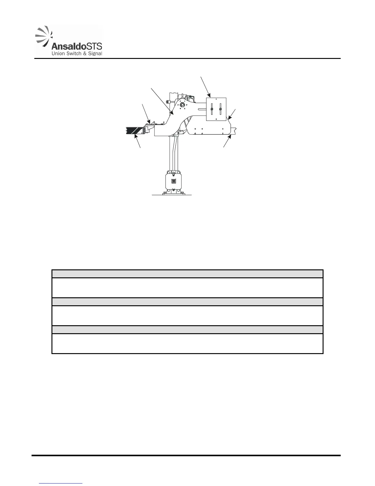
COUNTERWEIGHTS
GATE ARM
SUPPORT
CONVERSION
BRACKET
ASSEMBLY
HIGHWAY
CROSSING
GATE ARM
PEDESTRIAN
CROSSING
GATE ARM
PEDESTRIAN
GATE ARM
SHIELD
5A1.0011.00
Figure 2-1 - Completed Pedestrian Crossing Gate Arm Shield Installation
2.3. Power and Control Wiring
A maximum of 0.1 ohm resistance is allowed between the battery and the mechanism terminals. The
wiring requirements are given in Table 2-2:
Table 2-2 - Battery and Wire Requirements
Distance from Battery to Mechanism Cable Conductor Size
Up to 60 feet No. 9 AWG
60 to 120 feet No. 6 AWG
120 to 250 feet No. 4 AWG (or 2 #6 AWG)
Number of Cells (12-Volt System)
Gate Arm Length Lead Nickel-Iron Nickel-Cadmium
Up to 24 feet 6 9 9
25 to 42 feet 7 11 11
Number of Cells (24-Volt System)
Gate Arm Length Lead Nickel-Iron Nickel-Cadmium
Up to 24 feet 12 18 18
25 to 42 feet 14 22 22
For more detailed information, refer to Section 6. These three curves are based on the maximum gate
arm clearing times of 10, 15, and 20 seconds. These times are relative to the minimum voltage for
various cell quantities of lead acid batteries and nickel iron or nickel cadmium batteries. The curves
represent maximum gate arm clearing times relative to minimum battery cell voltages. Fully charged
batteries will decrease the time it takes for the gate arm to clear.