General Maintenance and Troubleshooting
2-18 SM 6495, Rev. 7, December 2008
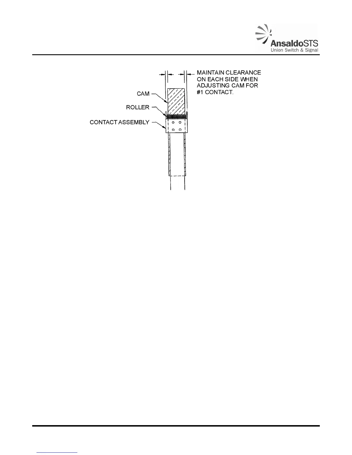
Figure 2-9 - Number 1 Contact
2.7. Gate Arm Ascent and Descent Time Test (12-Volt Systems)
This unit is equipped with a Power Down Module (PDM). The PDM is used in the power down
portion of operation (90° - 45°).
1. Apply 12 VDC to the control line of the gate mechanism. This will raise the arm automatically to
the clear position.
2. Measure the ascent time required to raise the arm from 0 to 90 degrees (horizontal to vertical
position). The ascent time is normally between 8 to 12 seconds.
3. With the arm in the vertical position, check that the gap between the buffer and segment gear is
about 1/8”.
4. Verify that the brake holds the arm in the up position.
5. Remove the control voltage (set DC voltage to 0). Removing the voltage will force the brake to
disengage and allow the arm to descend.
6. Measure the descent-time. The descent time should be adjusted to railroad specification, (generally
9 to 20 seconds). If necessary, adjust the snub resistor slide (refer to Figure 5-10 and Figure 5-11,
Item 40) and retest the descent time. The fixed limit resistor (refer to
Figure 5-10 and Figure 5-11,
Item 42) on the right side of electrical assembly limits the current to the motor during the first 45°
of the power down cycle.