Optional Equipment
SM 6495, Rev. 7, December 2008 4-1
4. OPTIONAL EQUIPMENT
4.1. Heater (Defroster)
Each heater kit (optional) uses a 25-watt resistive element. Refer to Table 4-1 for the appropriate heater
for your unit.
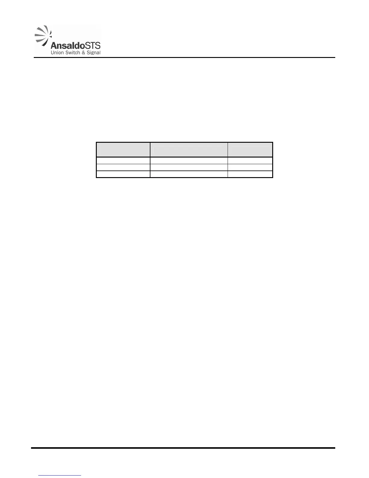
Table 4-1 - Model 95 Heater Kit Ordering Information
Heater Model
Number
Description Voltage
N467048-01 Model 95 Heater Kit 120 V
N467048-02 Model 95 Heater Kit 24 V
N467048-03 Model 95 Heater Kit 240 V
4.1.1. Installation Instructions for Model 95 Gate Mechanism Heater Kit
Use two each 4 - 40 screws, nuts and washers to mount resistor unit to left inside panel of the electrical
module bracket, just under the terminal board using two holes provided. (Some units may have the two
mounting holes on the right side of the electrical module bracket.)
Connect leads to terminal posts 2A and 3B on top of the terminal board (polarity is unimportant). If
heater kit is for a voltage of 50 volts or more, use the two insulator sleeves provided to cover the two
terminal posts together with the two insulator caps. It may be necessary to trim the length of the
insulator sleeves in order to accommodate the post lengths.
Connect two voltage supply leads (user provided) to 2A and 3B.
4.2. Maintenance Switch
The Maintenance Switch (
Figure 5-15) was developed to make replacing a gate arm easier and safer.
The switch allows the gate to be driven down without the weight of the gate arm to assist. Use of the
switch eliminates the need to connect jumpers inside the mechanism to drive the gate down.
If not installed, the maintenance switch may be ordered as part number N46709202
4.3. Severe Weather Shock Option
Gear Shock Assembly 1400 (PN N46701402) is a direct replacement for the standard gear shock
assembly used to maintain the gate mechanism’s gate arm position in the horizontal position.
This shock option offers a stiffer shock than standard. Its greater resistance minimizes the gate arm
dropping below horizontal due to increased weight from ice and snow sometimes encountered in
severe weather conditions.
After removal of the standard horizontal spring buffer shock, the severe weather shock is installed and
adjusted identical to the spring buffer as described in Section 2.4.1.