General Maintenance and Troubleshooting
2-20 SM 6495, Rev. 7, December 2008
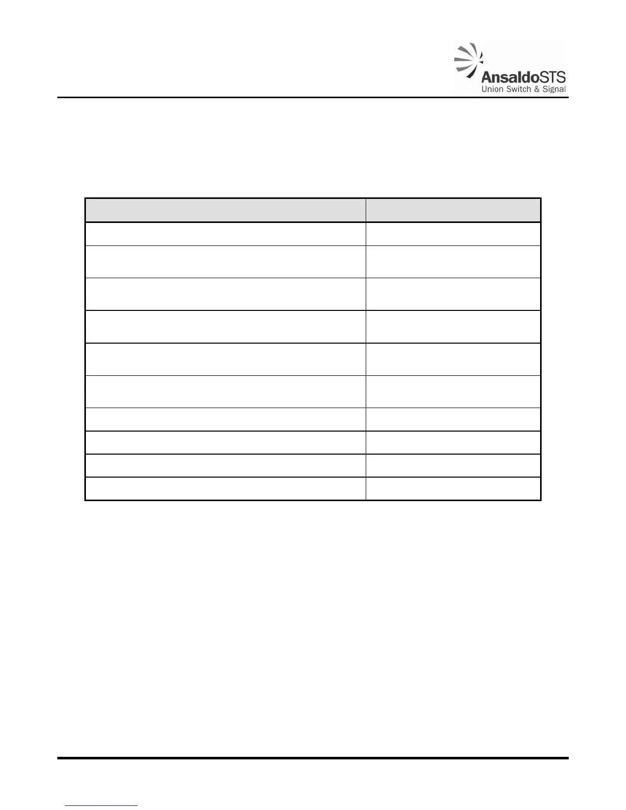
2.8. Test Checklist
Table 2-4 lists 10 items that should be tested and recorded after installation.
Table 2-4 - Test Checklist
Item Result
Torque Set Correctly
Ascent Time @ 12 or 24VDC Nom. (System Voltage)
(Maximum: 15 seconds)
*Ascent Current @ 12VDC Nom. (System Voltage)
(Maximum: 15 Amps)
*Ascent Current @ 24VDC Nom. (System Voltage)
(Maximum: 8 Amps)
Descent Time @ 12 or 24VDC Nom. (System Voltage)
(Maximum 12 seconds)
Cams Adjusted
#1 cam centered on roller cage. (
Figure 2-9)
Contacts Adjusted (Section 3.2.3)
Down (Front) Buffer
Up (Rear) Buffer With 1/8” Gap
Hold Clear Device (Brake) Operational (Section 3.2.5.3)
*Connect ammeter between 4B and 6B. Open gold nut on 5B to measure ascent current.