EasyManua.ls Logo

AnsaldoSTS 95 - Figure 3-4 - Proper Hardware Configuration on Terminal Posts 1 C, 2 C, and 3 C; Figure 3-5 - Location of Redesigned Power down Module on Terminal Posts 1 C, 2 C, and 3 C

Default Icon
100 pages
Print Icon
To Next Page IconTo Next Page
To Previous Page IconTo Previous Page
Loading...
General Maintenance and Troubleshooting
3-14 SM 6495, Rev. 7, December 2008
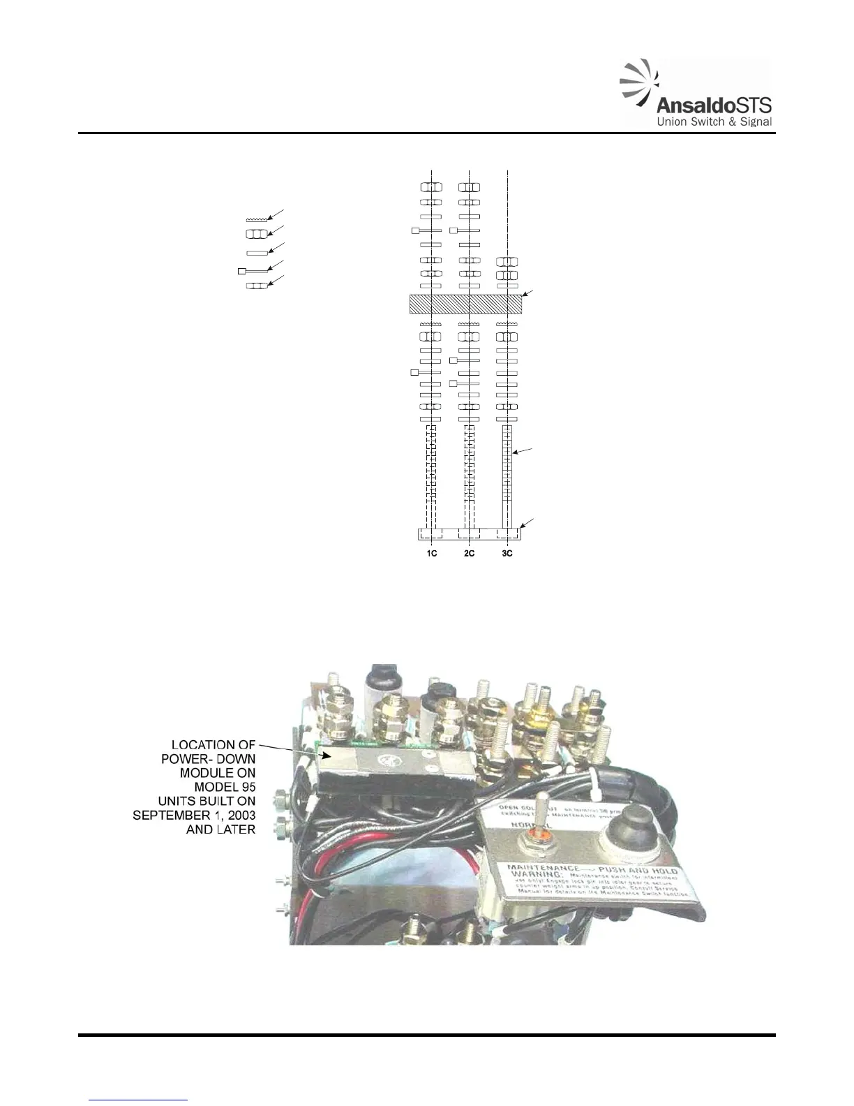
WASHER, LOCKING (STAR)
NUT, FULL
WASHER, FLAT
AMP CONNECTOR
NUT, HALF
POWER DOWN
MODULE
TERMINAL POST
TERMINAL BLOC
K
Figure 3-4 - Proper Hardware Configuration on Terminal Posts 1C, 2C, and 3C
Figure 3-5 - Location of Redesigned Power Down Module on
Terminal Posts 1C, 2C, and 3C

Table of Contents