General Maintenance and Troubleshooting
SM 6495, Rev. 7, December 2008 3-5
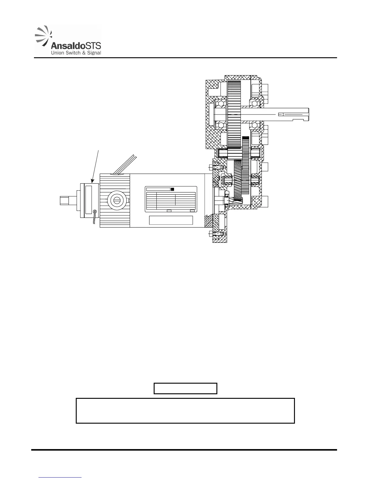
MOTOR# 32-999-2500-N09
CUST# 150-203-1509B
09272 INS# F3 AMB 25 C
°
(BISON ELEC. P/N)
(BISON GEAR P/N)
(MAX AMBIENT TEMP.
WITH CONT. RUNNING)
MADE IN USA
UNION SWITCH & SIGNAL
D.C.GEARMOTOR
MODEL
HP
VOLTS
AMPS
RPM
RATIO
TORQUE
011-500-9355-- REV.
1/6
12
15.0
30
55:1
290 IN LBS
INT. DUTY
SUPPLIER SEQ.NO.DATE MFG.
24 VDC XXXX
133-500-9255
UNION SWITCH & SIGNAL
HOLD CLEAR DEVICE
5A1.0014.00
Figure 3-1 - Hold Clear Device
1. Loosen the two (2) armature Allen head screws, using the Allen wrench (J0529800014) included in
the Model 95 Tool Kit (N46707001), so that the armature slides freely on the motor shaft (taking
care not to bend the armature springs when sliding).
2. Insert a 0.020” feeler gauge between armature and coil unit (preferably use two gauges and insert
one on each side of the shaft to assure that the armature does not cock sideways).
3. Tighten the two (2) Allen head screws.
4. Ensure the brake is operational.
3.2.5.3. Operational Test of Hold Clear Device (Factory/Shop Test)
WARNING
Remove power from gate mechanism before attempting to remove hold
clear device. Otherwise, bodily injury could result.