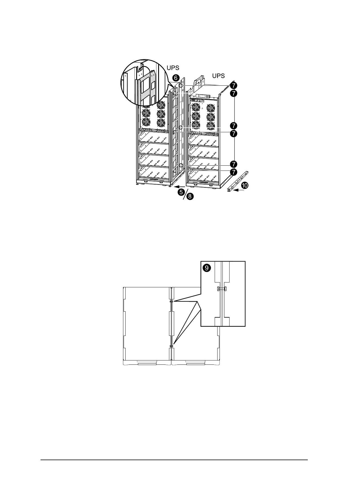
6.Inserttheinterconnectionplatesbetweenthetwoenclosures.Oneispositionedtowardthefront
andtheothertowardtherear.Noticehowthe“wings”ontheinterconnectionplatesrestinslotsat
thetopoftheinnerpanel.
7.AlignthetwoenclosuresandlevelthethreemarkedrowsofboltholesinUPS1withtheholes
inUPS2.
8.Pushthetwoenclosuresrmlytogether.
9.BoltthetwoenclosurestogetherusingthesixM6x25mmscrewsandnutssuppliedinthekit;join
oneholeatthefrontandoneholeattherearoftheenclosuresonthreelevels.
10.PositionthethirdU-shapedooranchoringbracketundertheadjacentenclosure(seeprevious
graphics)andinsertaminimumoftwoooranchoringM8screws(notprovided)throughthe
holesinthebottomoftheenclosureandthroughtheholesintheU-shapedooranchoringbracket,
andintothepredrilledoorholes,andthenfastenthescrews.
990–1598E-001
Smart-UPS™VT10–30kV A208/220VSingleandParallelInstallation
15
 Loading...

