5.FromthebottomofUPS2,runthePBuscablestotheslotsontheleftsideoftheenclosureand
upinsidethepanel.
6.TakeoutthePBuscablesandleavetheseunattached.
7.RuntheABuscablefromthemaintenancebypasspaneltotheslotsontheleftsideoftheenclosure
andupinsidethepanelthesamewayasforthePBuscables.
8.Reattachthecable-inletcoverplates.
9.Fastenthecableswithcableties.
Note:ProceedtheroutingofcablesintoUPS3andUPS4,ifapplicable.
UPSUnitsApartorBayedTogetherwithConduits
Note:Whenenclosuresareassembledwithinterconnectionplatesandboltedtogether,the
PBuscablescanberuninsidetheenclosuresandthenonlytheABuscablehastoberunin
aconduit(ifapplicable).
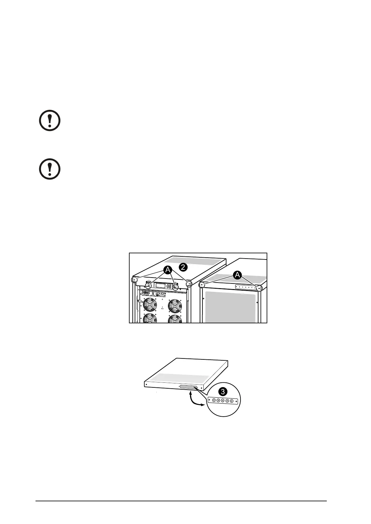
1.Removethefrontpanel(notshown).
2.Removethetopcover:
A.Loosenthesixscrewsofthetopcover(fouratthefrontandtwoattheback).
B.Liftupfromthebackandpushforwardtofreethecover.
C.LeavethecoverunattachedontopoftheUPS.
3.RemovetheconduitplateatthebackoftheUPScoveranddrillholescenteredinthesmall
pre-drilledholes.2cm(3/4in)isrecommendedforconduits.
4.RuntheABusandthePBuscablesthroughtheconduitholesintotheinsideofthetopcoveron
UPS1.LeavethecablesontopoftheUPS.
5.Attachconduitswith2cm(3/4in)ttings(notsupplied).
6.RunconduitswithPBuscablestoUPS2.Pullthecablesthroughthetopcoverconduitplateand
leavethecablesontopoftheUPSasshown.
7.AttachconduitstoUPS2with2cm(3/4in)ttings(notsupplied).
8.RuntheABuscables(inconduitsifapplicable)tothemaintenancebypasspanel.
42
Smart-UPS™VT10–30kV A208/220VSingleandParallelInstallation
990–1598E-001
 Loading...

