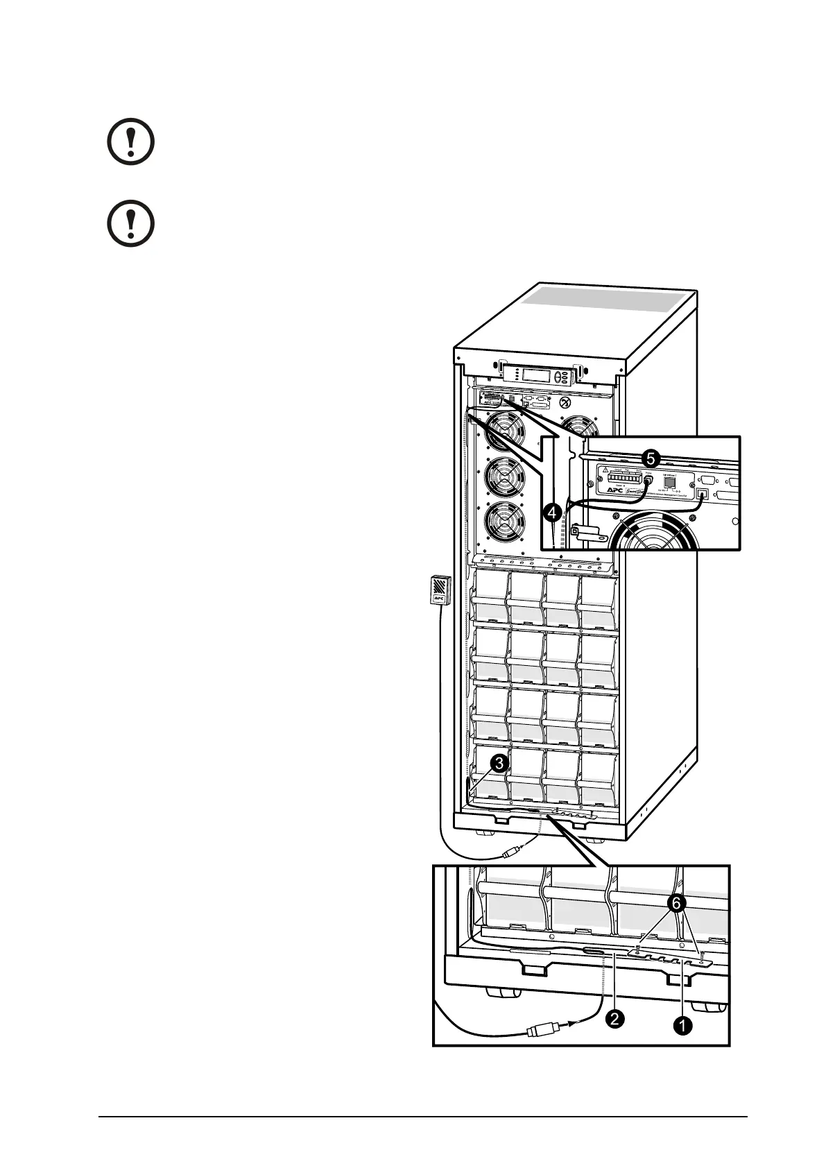
ConnectAPCCommunicationOptions
Note:Thecableroutingofthepowerchutesoftwareandthetemperaturesensorisidentical.
Note:ThetemperaturesensorisprovidedinaplasticbagattachedtothefrontoftheUPS
behindthefrontpanel.
1.Removethetwoscrewsfromthecable-inletat
thefrontandremovethecable-inletplate.
2.Guidethecablethroughtheholeinthebottom
plateandupthroughthecable-inlet.
3.Guidethecablethroughthesidepanelhole
andrunthecableupwardsinsidethepanel.
4.Pullthecableoutofthesidepanelthrough
theholeclosesttotheNetworkManagement
Cardarea.
5.Plugthecableintotheprobesocket/
PowerChuteinlet.
6.Reattachthecable-inletplate.
990–1598E-001
Smart-UPS™VT10–30kV A208/220VSingleandParallelInstallation
37
 Loading...

