33
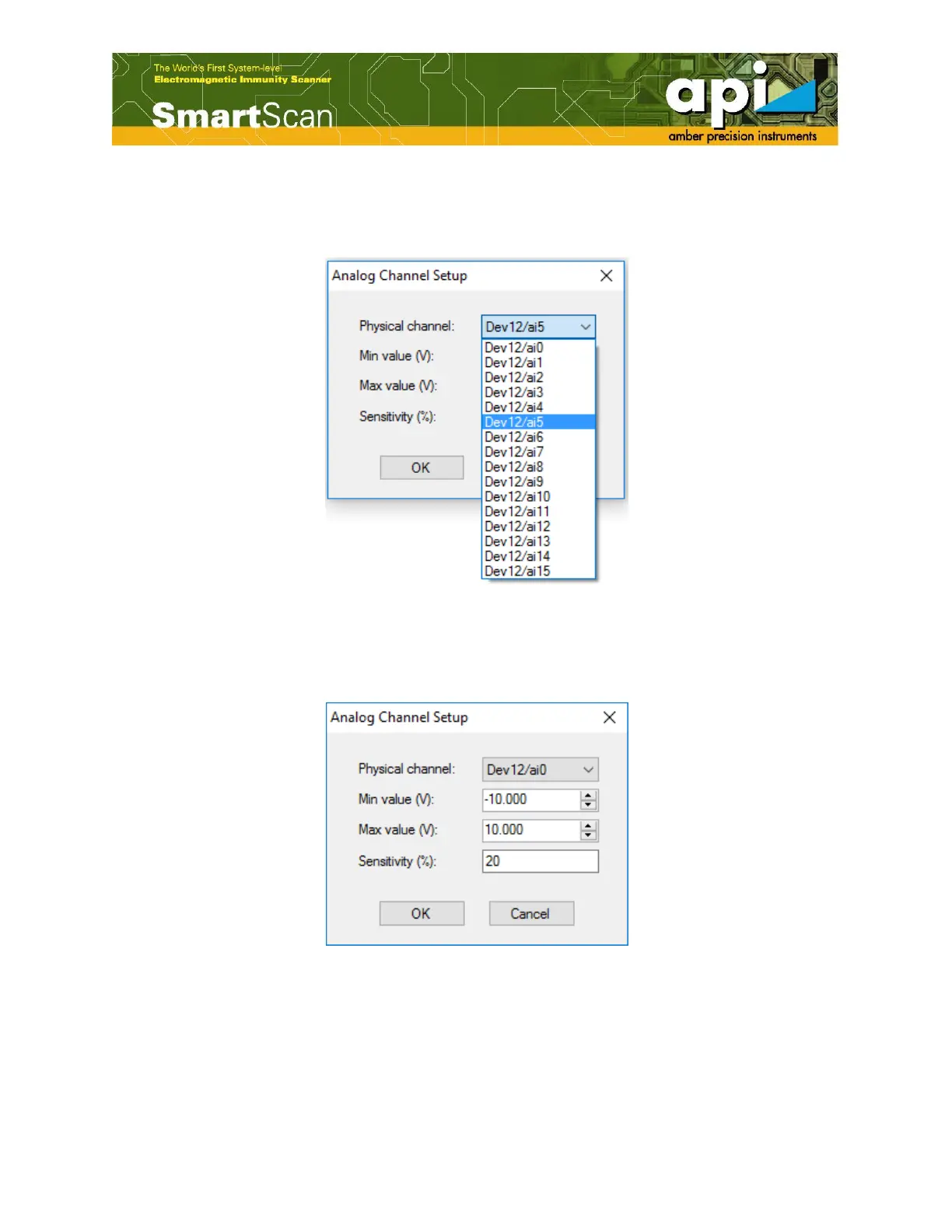
b. “Analog Channel Setup” window appears on the screen. “Physical channel” indicates the
physical address of the Analog channel, a list of channel addresses is provided in the drop-
down menu.
Figure 51: “Analog Channel Setup” window.
c. Usually the tested signal exists in a certain voltage range. User can set the measurement range,
the minimum and maximum voltage.
Figure 52: “Analog Channel Setup” window.
d. Select the corresponding address for the analog channel. Thus, one analog channel with the
address of “Dev12/ai5” is added to the group. In a similar manner, more analog channels can
be assigned to the same group. Maximum seven analog channels can be assigned.