Installation and Operation 54
CAUTION
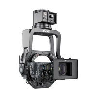
Fingers between top cover and Camera
Risk of crushing fingers.
Make sure that your fingers do not get between the top cover and the camera while checking the
tilt axis.
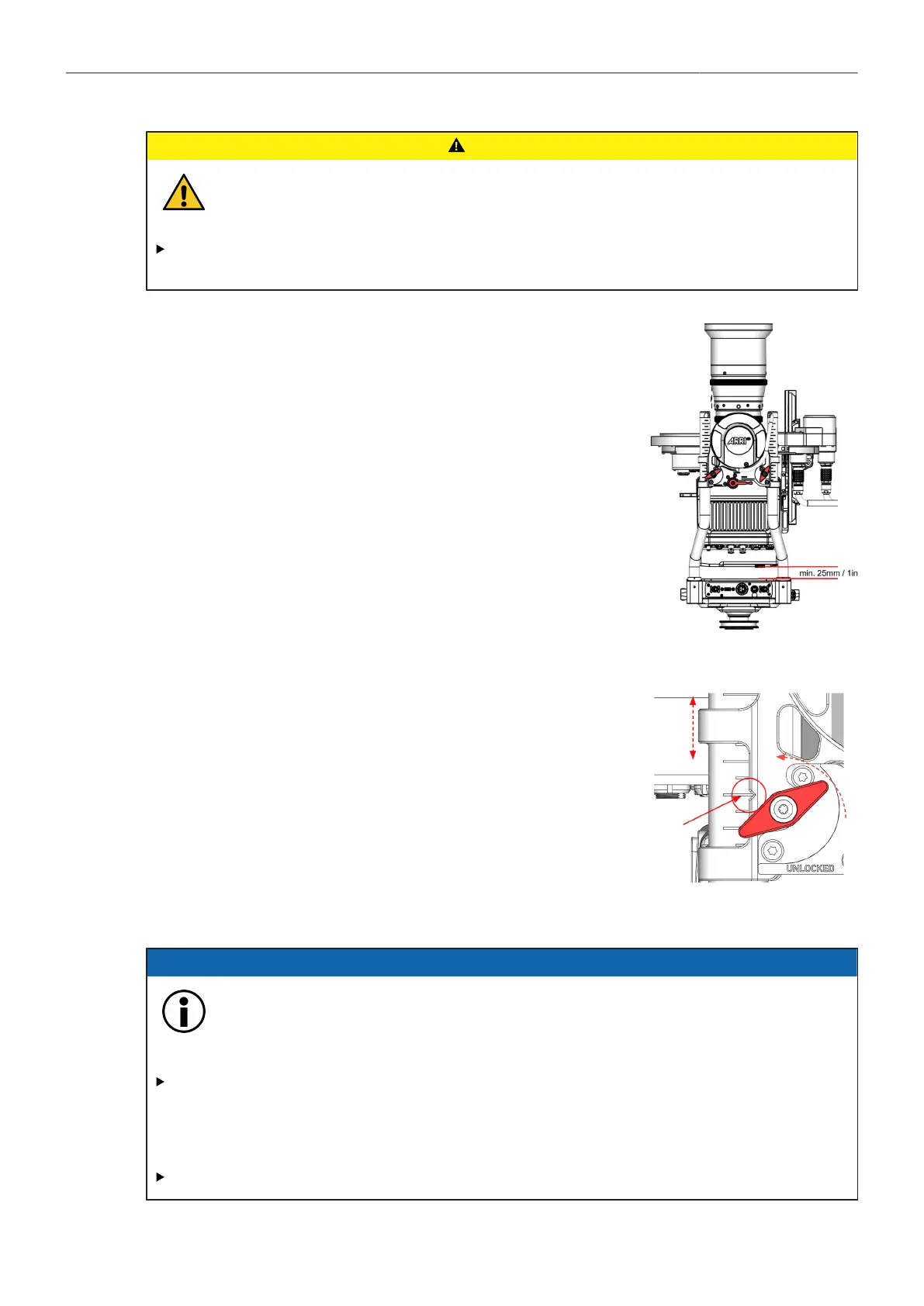
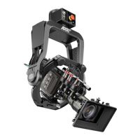
Minimum height of the tilt axis
4. To ensure enough clearance for the ring main cable, which is lo-
cated on the back of the camera, a minimum distance of approx.
25mm/1in be available.
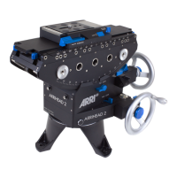
Height Adjustment Clamps
5. Open the four wing clamp screws and raise the complete tilt to-
gether with your assistant.
6. Make sure the small notch on all 4 rod clamps is exactly on the
same line!
7. Once the desired position has been reached, tighten all four wing
clamp screws.
8.1.5 Turning on the system
ADVICE
Powering TRINITY 2 Head, Top and Bottom Stage at the same time
This would cause more than the allowed amount of volts to flow through the ARTEMIS 2
and TRINITY 2. Risk of damage to the accessories.
Only use the Top Stage TST-2 in combination with the Battery Hanger Module BHM-2 for the
internal power supply of the TRINITY 2 Head.
Alternatively, an external power source can be used to power the TRINITY 2 head.
DO NOT combine the internal with an external power supply!