SECTION 7 DIAGNOSTICS AND TROUBLESHOOTING
______________________________________________________________________
7-1
SECTION 7
7 DIAGNOSTICS AND TROUBLESHOOTING
____________________________________________________
INTRODUCTION
This section details:
• The Diagnostic Menu
• System and patient messages and appropriate operator actions
• What to do if the A-2000 requires service.
7.1 THE DIAGNOSTIC MENU
The Diagnostic Menu is designed to help you trace the source of problems you may be
experiencing with the A-2000 system. It may be accessed by selecting “Advanced Setup” from
the Setup Menu, then selecting “Diagnostic Menu.”
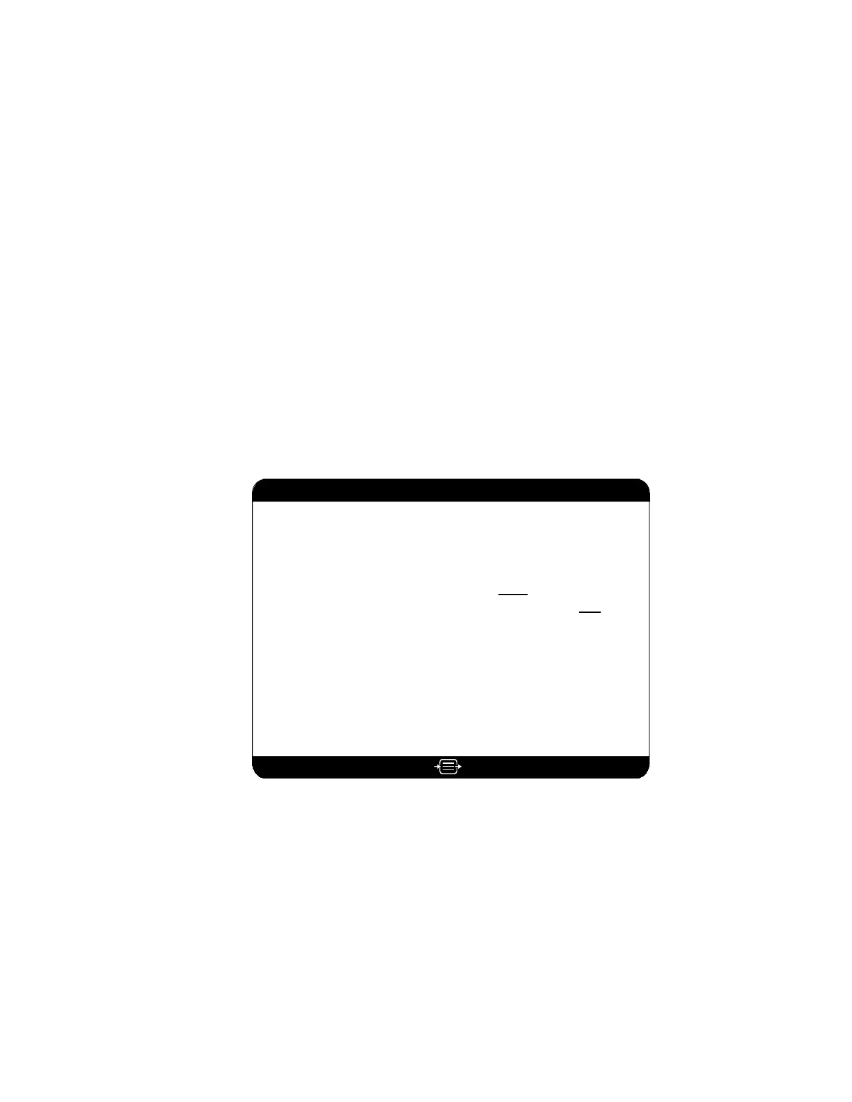
Diagnostic Menu
to ExitPress
DSC Self Test
Display Self Test
Sensor Data Display
Return to Advanced Setup Menu
Diagnostic Codes ONOFF
Impedance Checking OFF ON
System Revision
Host Revision
BIS Engine Revision
FPGA Revision
Run Time . . . . .
Serial Number
BIS Usage
. . . . . . . . . . 3.00
. . . . . . . . . . . . 3.00
. . . . . . 1.13
. . . . . . . . . . . 1.06
. . . . . . . . 567891
. . . . . . . . C002033
. . . . . . . . . . . . . . . 125
PIC/Sensor Type . . . . . . . . . . . . .4
DSC Type . . . . . . . . . . . . . . . . . .8
Clear Data
System Configuration Menu
DSC FPGA . . . . . . . . . . . . . 2.0.1.6
Figure 25 The Diagnostic Menu