The following example illustrates this point:
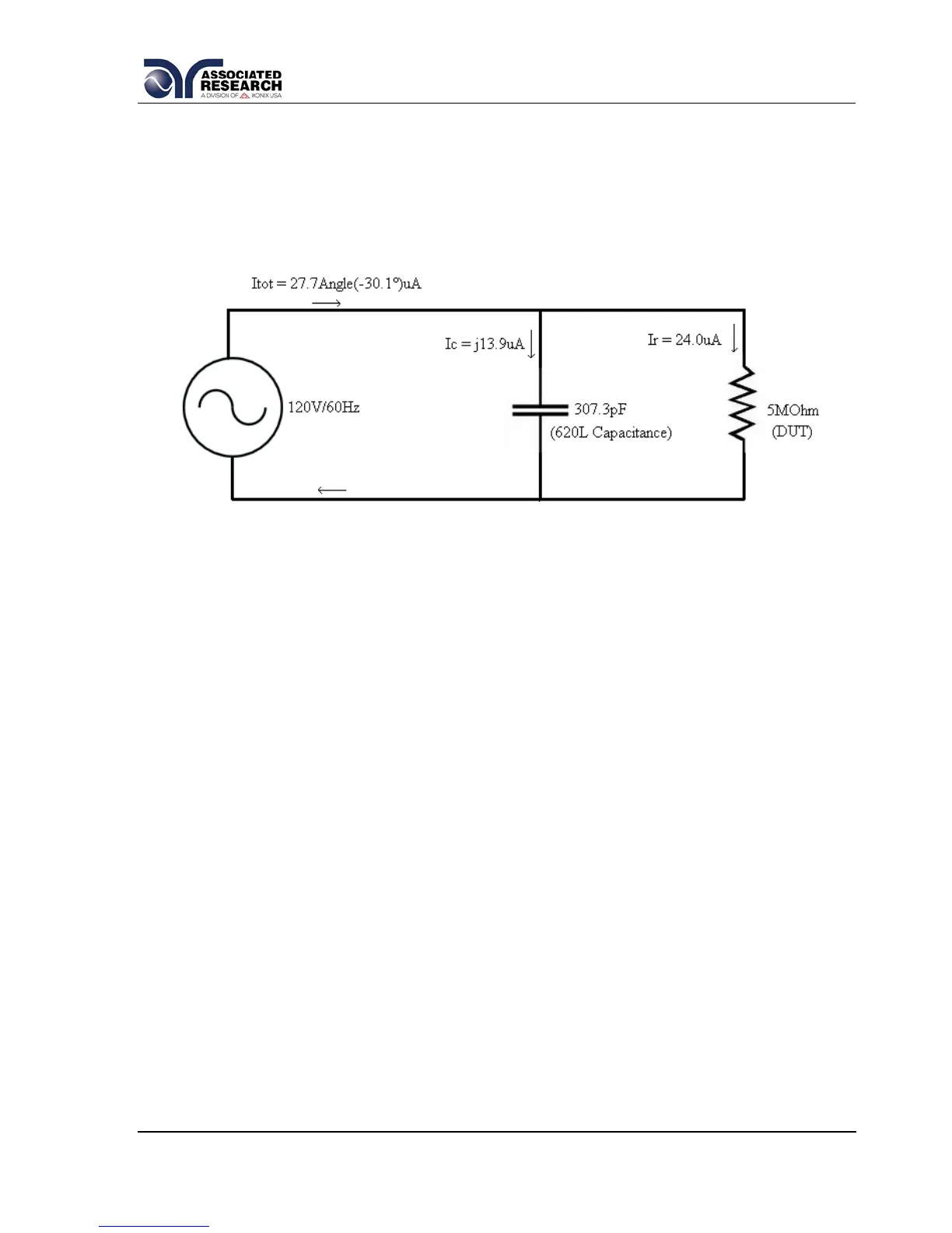
Consider the network in Figure 1 as a simulation for a 620L system and DUT. The
network consists of a 307.3pF capacitor to represent the capacitance of the 620L
system. This is in parallel with a 5MΩ resistor to represent the DUT. The voltage
source is generating 120V at 60Hz.
Figure 1
The two components have the same potential applied across them. Each element will
have its own associated current. Current flowing through the capacitor will be denoted
as Ic and current flowing through the resistor will be denoted as Ir. The vector
summation of these currents is the total current in the system, Itot. The theoretical
calculations are shown below:
Ir = V/R = 120V/5,000,000Ω = 24.0uA
Current through the capacitor requires an extra calculation of the capacitive
reactance:
Capacitive Reactance = Xc = 1/(2ПfC) where f is frequency and C is the capacitance.
Xc = 1/(2П*(60Hz)*(307.3pF)) = 8,631,898Ω
So Ic = V/Xc = 120V/8,631,898Ω = j13.9uA.
Then the total current Itot = 24.0uA - j13.9uA. This breaks down into a magnitude and
phase angle:
Magnitude of Itot = |Itot| = √(24.0^2 + 13.9^2) = 27.7uA
Phase Angle = Angle(Itot) = Tan-1(-j13.9/24.0) = -30.1°
Therefore Itot = 27.7Angle(-30.1)uA