Using the Offset feature on this network, the 620L displays the following:
Offset = 13.9uA
The test is then run. The 620L displays the following:
Displayed Current = 24.0uA
This is a result of the vector sum calculation: 24.0uA = √((27.7uA)^2 – (13.9uA)^2)
The Displayed Current is the current flowing through the resistor. This is because the
phase angle of the 620L system can be considered to be purely capacitive (-90°) and
the phase angle of the resistance is 0°. Since the phase angle between the 620L
system leakage current and the DUT leakage current is 90°, the LLT Offset works
optimally for this application.
If the phase shift between the 620L system and the DUT is not 90°, the Displayed
Current value will not be a valid representation of the leakage current flowing through
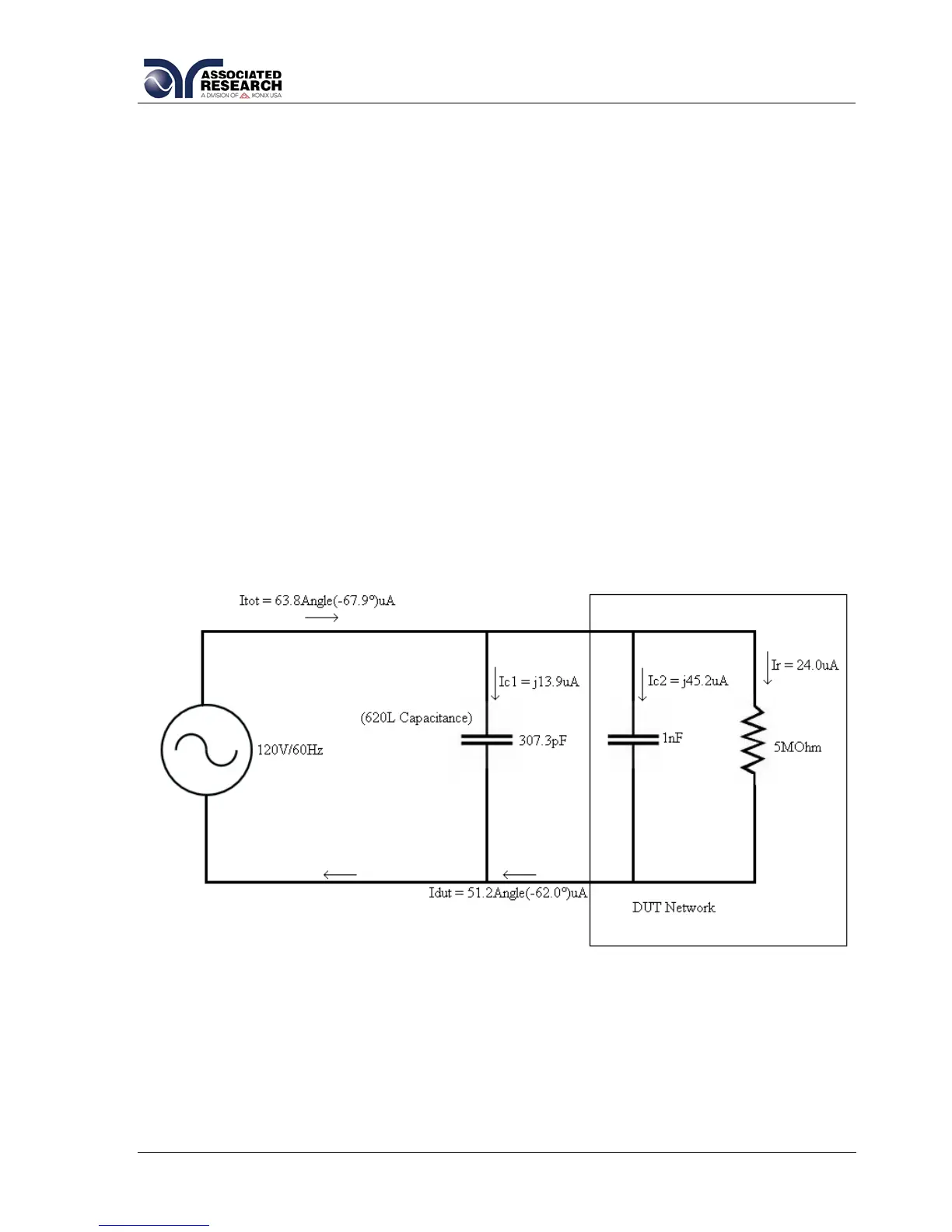
the DUT. Consider a second test circuit. This test circuit is shown in Figure 2. The
620L system is modeled by the 307.3pF capacitor. In this case, the DUT is modeled
by the parallel combination of a 1nF capacitor and a 5MΩ resistor.
Figure 2
From the calculations of the first circuit network, it is known that the capacitive
reactance of the 307.3pF capacitance is Xc1 = 8,631,898Ω. The capacitive reactance
of the 1nF capacitor is shown below:
Xc2 = 1/(2ПfC2) = 1/(2П*(60Hz)*(1nF)) = 2,652,582 Ω
The current through each branch of the network: