Manual, F/T Sensor, Ethernet Axia
Document #9610-05-Ethernet Axia-09
Pinnacle Park • 1031 Goodworth Drive • Apex, NC 27539 • Tel:+1 919.772.0115 • Fax:+1 919.772.8259 • www.ati-ia.com
36
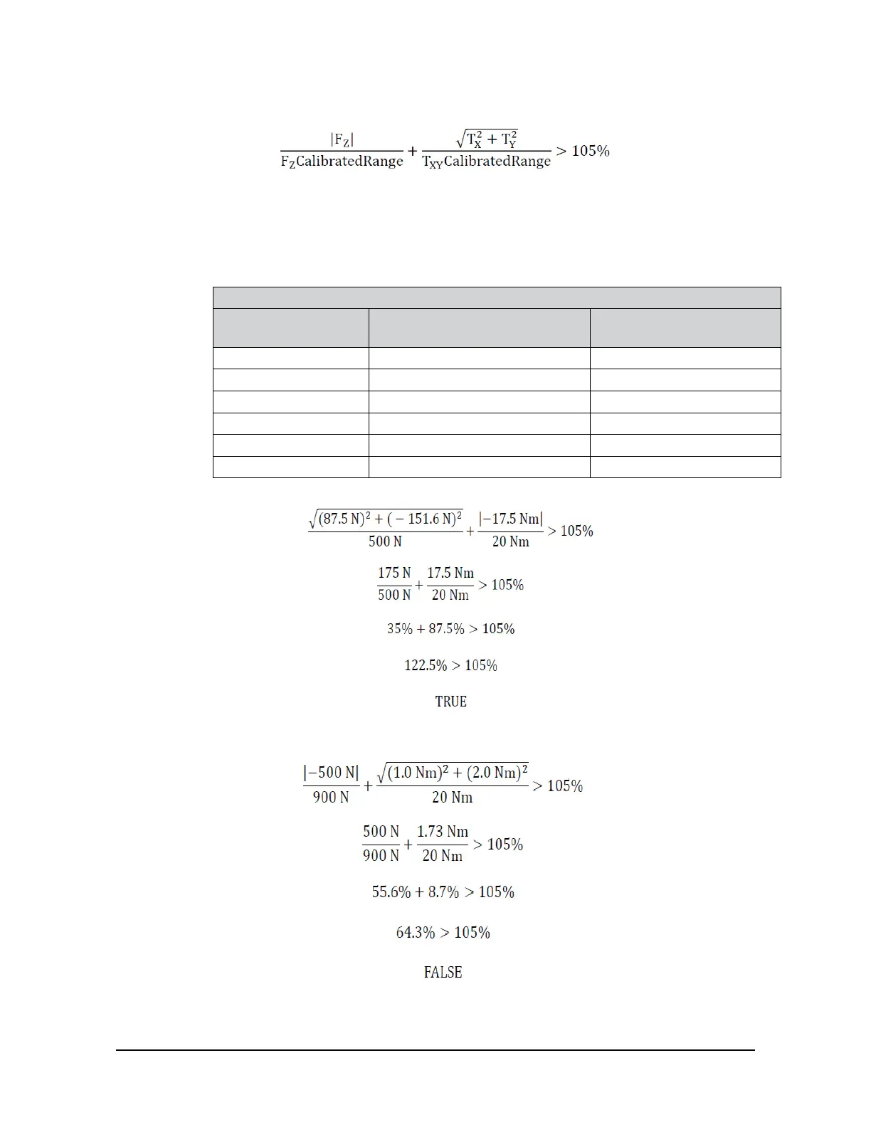
• The total percentage of the calibrated range used by F
z
and T
xy
axes is greater than 105%. Refer
to the following F
z
T
xy
equation.
Refer to Section 15.3—Calibration Ranges for the calibrated ranges that are used in the
preceding equations.
For example:
An Axia80-M20 sensor that uses calibration range 0 (SI-500-20) is subjected to the following loads
and has the following calibration ranges:
Table 4.8—Example of Force/Torque Out of Range
Axis Applied Load
Calibration Range 0
Table 15.3 Value
F
x
87.5 N 500 N
F
y
-151.6 N 500 N
F
z
-500.0 N 900 N
T
x
1.0 Nm 20 Nm
T
y
2.0 Nm 20 Nm
T
z
-17.5 Nm 20 Nm
The F
xy
T
z
equation simplies as follows:
The F
z
T
xy
equation simplies as follows:
Because the F
xy
T
z
equation simplied to TRUE, bit 30 in Table 4.7 is set.
 Loading...
