Manual, F/T Sensor, Ethernet Axia
Document #9610-05-Ethernet Axia-09
Pinnacle Park • 1031 Goodworth Drive • Apex, NC 27539 • Tel:+1 919.772.0115 • Fax:+1 919.772.8259 • www.ati-ia.com
22
3.5 Pin Assignment for the Ethernet and Power Connection
CAUTION: Ensure the cable shield is properly grounded. Improper shielding on the
cables can cause communication errors and inoperative sensor.
Pin assignment for the power and Ethernet connections on the sensor and cables are in the following
sections. For supply voltage ratings, refer to the following table or Section 15.2—Electrical Specications.
Table 3.3—Power Supply
1
Power Source
Voltage Power Consumption
Minimum Nominal Maximum Maximum
DC Power 12 V 24 V 30 V 1.5 W
Notes:
1. The power supply input is reverse polarity protected. If the power and ground to the power supply
inputs are plugged in reverse, then the reverse polarity protection stops the incorrectly wired supply
input from damaging or powering on the sensor.
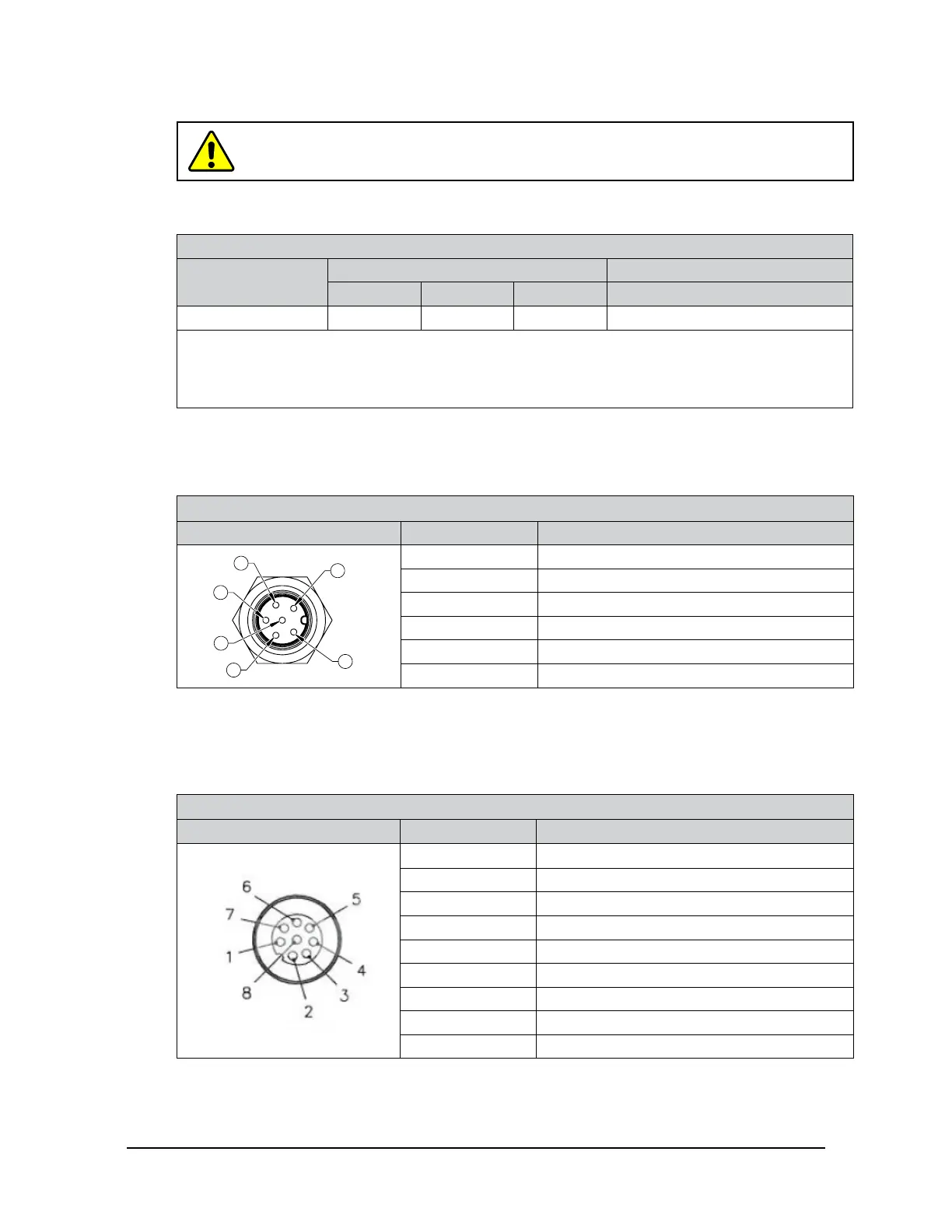
3.5.1 Pin Assignment : 6-pin Male M8 ZC22 Sensor Connector
Signals and corresponding pin numbers for the 6-pin male M8 ZC22 sensor connector are in the
following table:
Table 3.4—Pin Assignment for the 6-pin, Male, M8 ZC22 Connector (Power and Ethernet)
Connector Schematic Pin Number Signal
1
2
6
3
4
5
1 TX+
2 TX-
3 RX+
4 RX-
5 V +
6 V -
3.5.2 Pin Assignment : 8-Pin Male M12 ZC28 Connector
For the 8-pin male M12 ZC28 connector on cable P/N 9105-C-ZC22-ZC28-X that connects
to cable P/N 9105-C-ZC28-U-RJ45S-X, the signals and corresponding pin numbers are in the
following table.
Table 3.5—Pin Assignment for the 8-pin, Male, M12 Connector (Power and Ethernet)
Connector Schematic Pin Number Signal
1 No Connection
2 V +
3 V -
4 TX-
5 RX+
6 TX+
7 No Connection
8 RX-
Shield Shell
 Loading...
