Manual, F/T Sensor, Ethernet Axia
Document #9610-05-Ethernet Axia-09
Pinnacle Park • 1031 Goodworth Drive • Apex, NC 27539 • Tel:+1 919.772.0115 • Fax:+1 919.772.8259 • www.ati-ia.com
26
4. Operation
Information required when using the software to operate the Axia Ethernet sensor is in the following sections.
Communicating with the sensor requires knowledge of Ethernet standards and operation. Commands to operate and
congure the sensor can be sent in the following ways:
• ATI website (Section 5—Connecting Through Ethernet and Section6—ConguringtheSensorwiththe
Ethernet Axia Web Pages)
• ATI demo program: Section 7—Java
®
Demo Application
• Console through Telnet (Section 8—Console Interface Through Telnet)
• CGI (Section 9—Common Gateway Interface(CGI))
4.1 Sensor Environment
CAUTION: Damage to the outer jacketing of the sensor cable could enable moisture
or water to enter an otherwise sealed sensor. Ensure the cable jacketing has not
deteriorated to prevent sensor damage.
NOTICE: Sensorsmayreacttoexceptionallystrongandchangingelectromagneticelds,such
asthoseeldscreatedbymagneticresonanceimaging(MRI)machines.
The user must ensure that the dust and water in the environment does not exceed the IP64
rating of the sensor.
4.2 LED Outputs
The Ethernet Axia sensor provides (3) LED units for Link/Activity (L/A), Diagnostic (DIAG), and Status.
Each of these units can be off, red, green, or both red and green (orange).
4.2.1 Self-Test LED Sequence
When the user applies power to the sensor, the sensor completes a self-test, during which the LEDs
individually turn on in the following sequence:
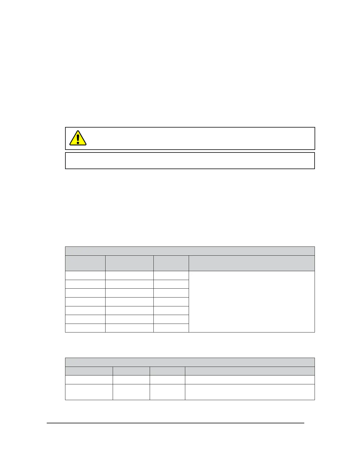
Table 4.1—Self-Test LED Sequence
Sequence
Order
LED State Duration
1 All Off
Approximately one second for each LED.
2 Status Red
3 DIAG Red
4 L/A Red
5 Status Green
6 L/A Green
7 DIAG Green
4.2.2 L/A LED
One LED signals link/activity on the Ethernet port as follows:
Table 4.2—L/A LED
LED State Link Activity Condition
Off No No Ethernet link/activity is not detected.
Green Yes Yes
Ethernet link/activity is detected. The light stays
green for 5 seconds after any link activity.
 Loading...
