Manual, F/T Sensor, Ethernet Axia
Document #9610-05-Ethernet Axia-09
Pinnacle Park • 1031 Goodworth Drive • Apex, NC 27539 • Tel:+1 919.772.0115 • Fax:+1 919.772.8259 • www.ati-ia.com
13
2. Product Overview
The Ethernet Axia Force/Torque (F/T) sensor measures six components of force and torque (F
x
\ F
y
\ F
z
\ T
x
\ T
y
\
T
z
) and communicates this data to customer devices via Ethernet. The user can communicate with the sensor from
a console through Telnet or CGI. A user can also communicate with the sensor through the sensor’s internal ATI
webpages, the ATI demo program, or an ATI-provided LabVIEW
®
code.
The sensor’s mounting side attaches to a mounting interface plate, which mounts to the customer robot. The tool
side attaches to the customer tooling. Both the mounting and tool sides have a 71.12 mm bolt circle pattern with (6)
M5 tapped holes and (2) slip t dowel holes (refer to Section 16—Drawings for more information). The sensor is
IP64 rated. An M8 6-pin male connector is for power and Ethernet. For the pin assignments, refer to Section 3.5—
Pin Assignment for the Ethernet and Power Connection for Ethernet and power.
The Ethernet Axia sensor offers the following features:
• Calibrated force/torque data
• Bias functionality
• Programmable low-pass ltering with cut-off frequency
• Tool transformation
• Thresholding
• LED indicator for Link/Activity (L/A), Diagnostic (DIAG), and Status
• Compatible with the ATI Net F/T sensor UDP interface and Java demo application (refer to Section 12—
UDP Interface Using RDT, Section 7—Java® Demo Application, and the 9620-05-NET F/T manual for
more information)
• Compatible with parts of the ATI Net F/T web interface (refer to Section6—ConguringtheSensorwiththe
Ethernet Axia Web Pages and the 9620-05-NET F/T manual for more information)
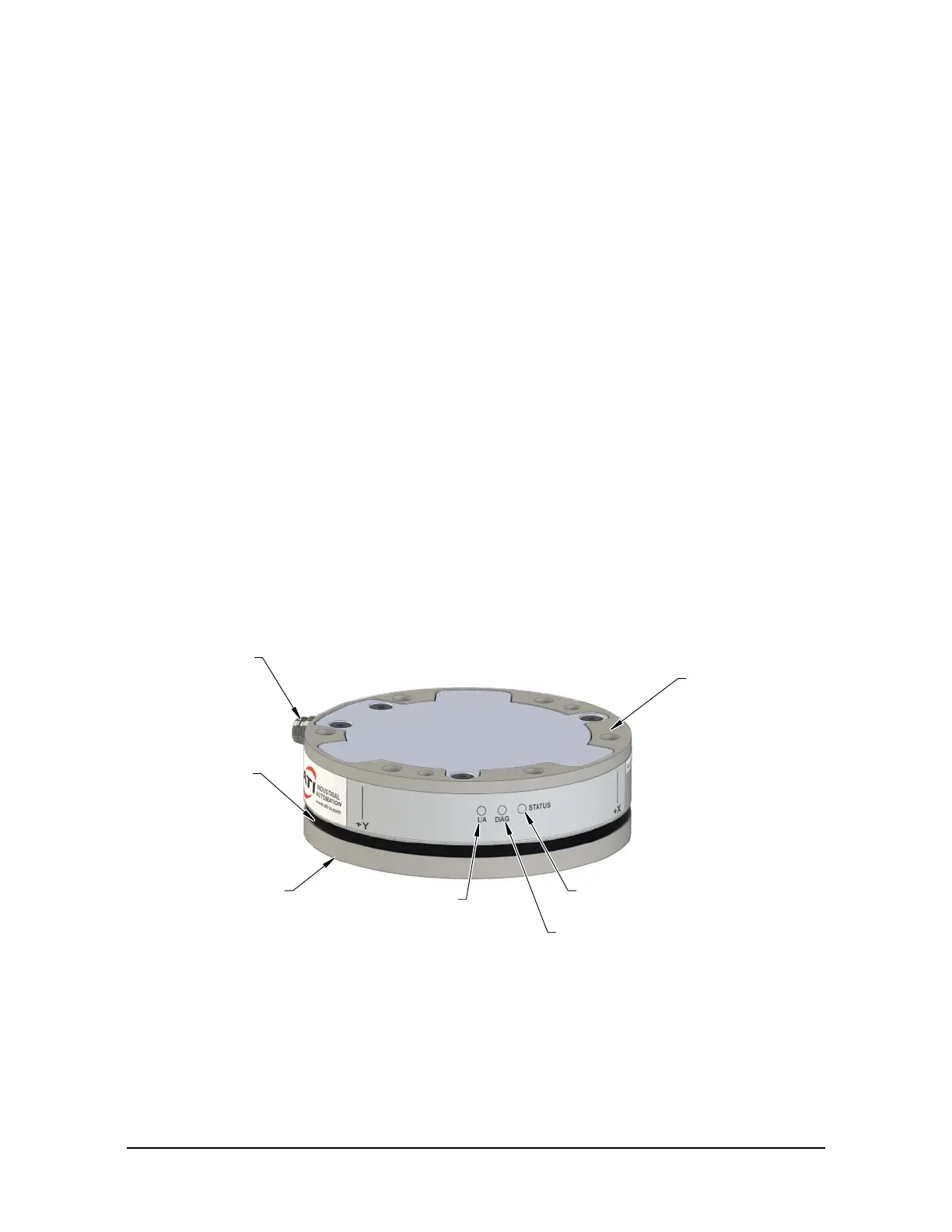
Figure 2.1—Ethernet Axia F/T Sensor
6-pin Male M8
Power and Ethernet
Connector
IP64 Seal
Tool Side
(For Customer
Tooling)
Link/Activity (L/A)
LED
Diagnostic (DIAG) LED
Status LED
Mounting Side
to the robot or fixture.
 Loading...
