Manual, F/T Sensor, Ethernet Axia
Document #9610-05-Ethernet Axia-09
Pinnacle Park • 1031 Goodworth Drive • Apex, NC 27539 • Tel:+1 919.772.0115 • Fax:+1 919.772.8259 • www.ati-ia.com
52
6.7 Communication Page (comm.htm)
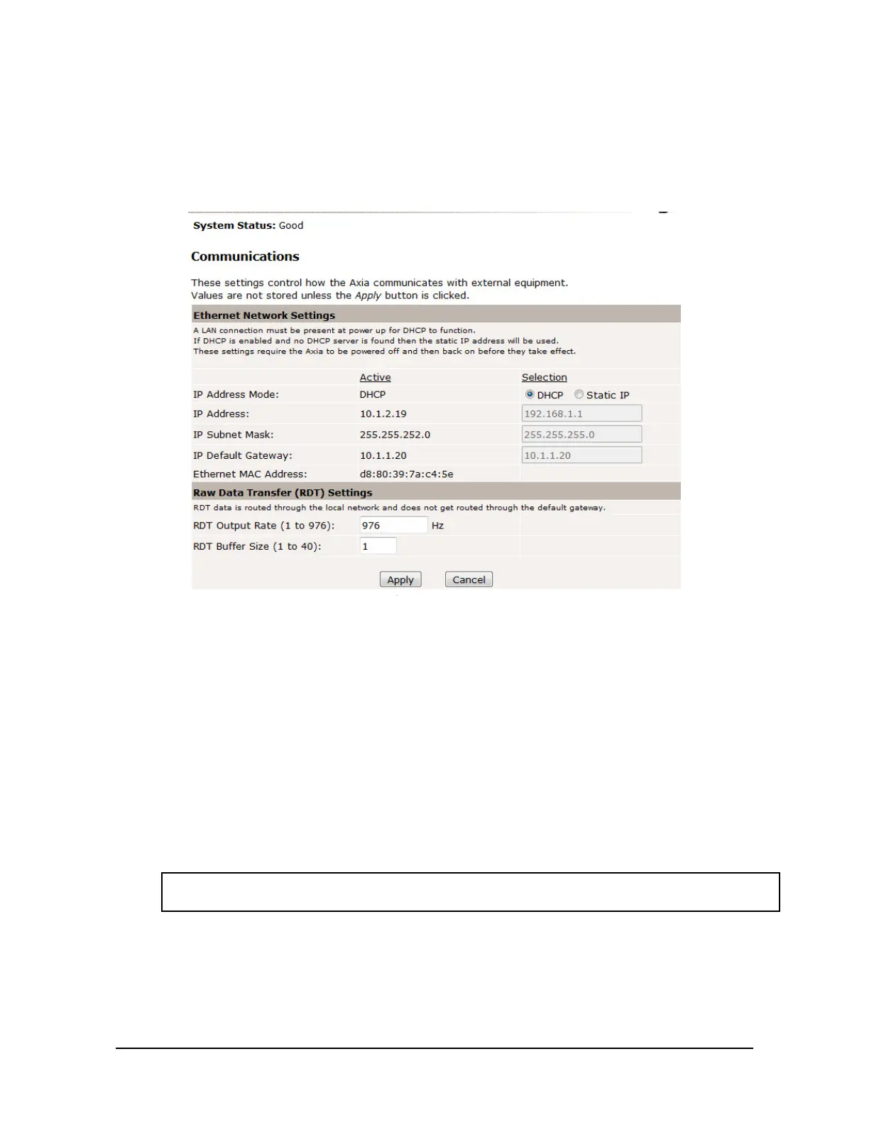
On the Communication page, the user may view and edit the system’s Ethernet networking options.
Usually these settings are set once when the user rst setup the system and do not need to be changed later
A detailed overview of setting up Ethernet communications with the sensor is in Section 5—Connecting
Through Ethernet.
Figure 6.8—Communications Page
The descriptions for the elds on the Communications page, Figure 6.8, are the following:
Ethernet Network Settings:
IP Address Mode: The user can congure the IP address of the sensor (refer to Section 5.1—IP Address
Conguration for Ethernet).
Static IP Address: The user can set the static IP address (refer to Section 5.1—IP Address
CongurationforEthernet).
Static IP Subnet Mask: This eld is for the subnet mask portion of the IP address. Many networks use the
default 255.255.255.0. Users should contact their IT department to know what static
IP subnet mask to assign.
IP Default This eld is for the default gateway. Users should contact their IT department to
Gateway: know what default gateway to assign.
Ethernet MAC A unique address that given to the sensor at the time of manufacture. This address
Address: uniquely identies this sensor from other sensors and other Ethernet devices.
NOTICE: Detailed information about RDT settings with a UDP interface is in Section12—UDP
Interface Using RDT.
Raw Data Transfer (RDT) Settings:
RDT Output Rate: In this eld, the user can set the RDT ouput rate from 1 to the value of the ADC
sampling rate in Section 4.3—Sample Rate.
RDT Buffer Size: In this eld, the user can set the RDT buffer size to a value from 1 to 40.
 Loading...
