Manual, F/T Sensor, Ethernet Axia
Document #9610-05-Ethernet Axia-09
Pinnacle Park • 1031 Goodworth Drive • Apex, NC 27539 • Tel:+1 919.772.0115 • Fax:+1 919.772.8259 • www.ati-ia.com
37
4.8.2 How to Interpret Hexadecimal Output for the Status Code
The user converts hexadecimals to a 32-bit binary number that correlates to a status code from
Table 4.7. An example of bit patterns are in the following table.
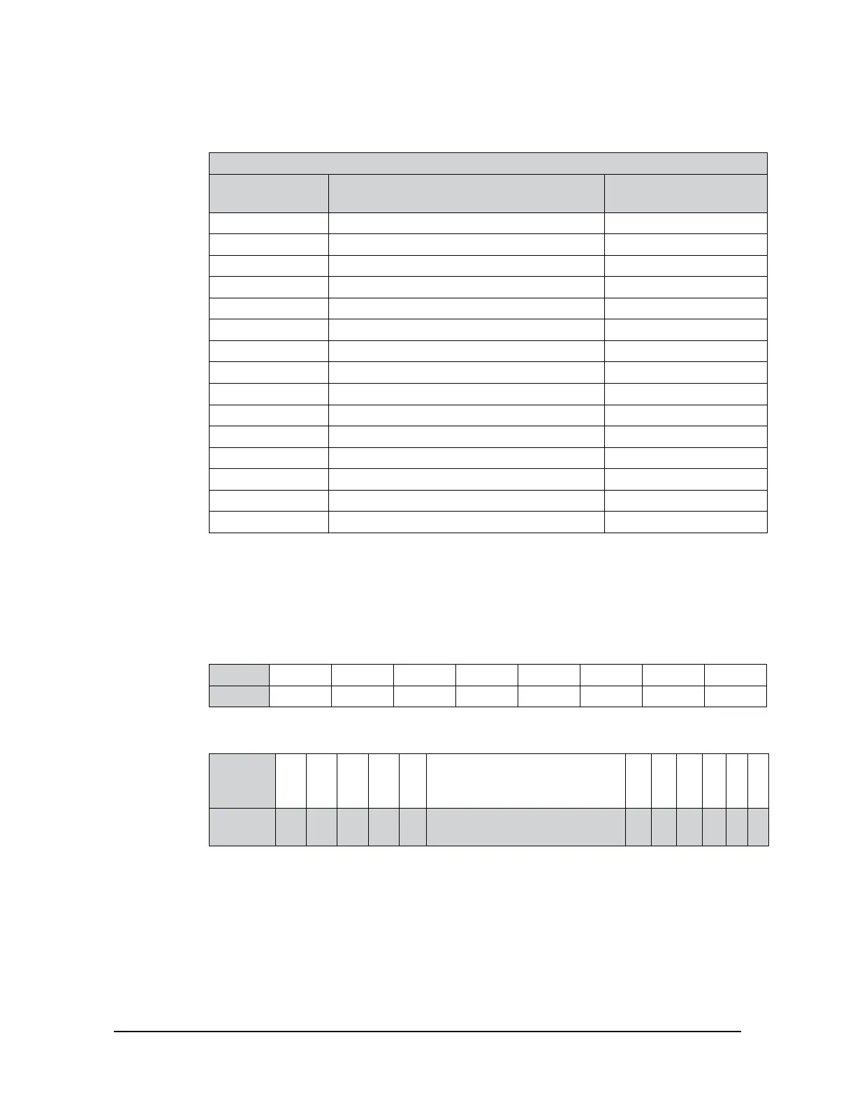
Table 4.9—Bit Pattern Examples
Bit Number
Simple Description
(refer to Table 4.7)
Bit Pattern
0 Temperature 0x80000001
1 Supply voltage 0x80000002
2 Broken gage 0x80000004
3 Busy bit 0x80000008
4 Reserved N/A
5 Other 0x80000020
6 to 15 Reserved N/A
16 Monitor condition latched 0x00010000
17 to 26 Reserved N/A
27 Gage out of range 0x88000000
28 Simulated error 0x10000000
29 Calibration checksum error 0xA0000000
30 F/T out of range 0xC0000000
31 Any error 0x80000000
-- Healthy 0x00000000
The bit pattern can be different if more than one error is present. For example, a user issues
this console command (refer to Section 8.3—Secondary Commands for the Query “c”
or “s” Command):
user: s !
response: 80000005
Using a free online calculator, convert the hexadecimal number to a binary number:
Hex 8 0 0 0 0 0 0 5
Binary 1000 0000 0000 0000 0000 0000 0000 0101
The binary number has 32-bits total. The least signicant bit is on the right end of the following
table. “1” means the bit is on. “0” means the bit is off.
Binary
Number
1 0 0 0 0 000 0000 0000 0000 0000 00 0 0 0 1 0 1
Bit
Position
31 30 29 28 27 26 to 6 5 4 3 2 1 0
So in this example, bit number 0, 2 and 31 are on. According to the preceding table, the sensor has
a “temperature”, “broken gage error”, and “any error” status codes (refer to Table 4.7).
 Loading...
