Manual, F/T Sensor, Ethernet Axia
Document #9610-05-Ethernet Axia-09
Pinnacle Park • 1031 Goodworth Drive • Apex, NC 27539 • Tel:+1 919.772.0115 • Fax:+1 919.772.8259 • www.ati-ia.com
89
14.8.4 Avoid Logging the Host to a Company Network
Being logged onto a network requires the periodic access to the Ethernet interface by processes
other than the measurement application and can lead to loss of UDP packages.
14.8.5 Use a Dedicated Network
Placing the sensor on a dedicated Ethernet network with no other devices on the network, other
than the host computer, removes data collisions and gives the best network performance.
15. Specications
The requirements for the Ethernet Axia sensor interface are covered in the following sections.
15.1 Environmental Conditions
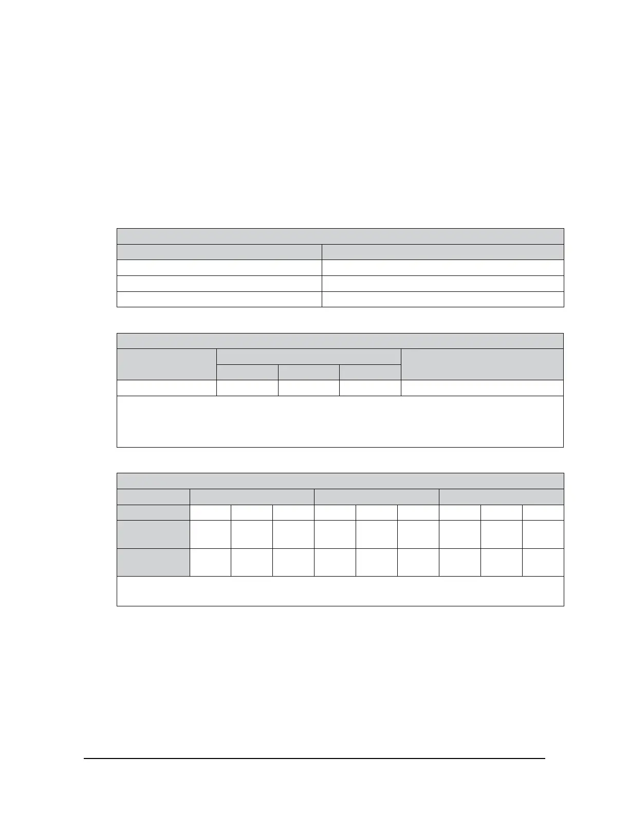
Table 15.1—Environmental Conditions
Parameter Value
Storage Temperature, °C -20 to +85
Operating Temperature, °C 0 to +65
Relative Humidity <95%,non-condensing
15.2 ElectricalSpecications
Table 15.2—Power Supply
1
Power Source
Voltage
Maximum Power Consumption
Minimum Nominal Maximum
DC Power 12 V 24 V 30 V 1.5 W
Notes:
1. The power supply input is reverse polarity protected. If the power and ground to the power supply
inputs are plugged in reverse, then the reverse polarity protection stops the incorrectly wired supply
input from damaging or powering on the sensor.
15.3 Calibration Ranges
Table 15.3—Calibration Range 0 and Calibration Range 1
Model Axia80-M8 Axia80-M20 Axia80-M50
Parameter Fxy Fz Txyz Fxy Fz Txyz Fxy Fz Txyz
Calibration
Range 0
150 N 470 N 8 Nm 500 N 900 N 20 Nm 1200 N 2000 N 50 Nm
Calibration
Range 1
75 N 235 N 4 Nm 200 N 360 N 8 Nm 480 N 800 N 20 Nm
Notes:
1. Each Ethernet Axia80 sensor is calibrated with both of these calibration ranges.
 Loading...
