Manual, F/T Sensor, Ethernet Axia
Document #9610-05-Ethernet Axia-09
Pinnacle Park • 1031 Goodworth Drive • Apex, NC 27539 • Tel:+1 919.772.0115 • Fax:+1 919.772.8259 • www.ati-ia.com
21
6. Properly restrain and route the power and Ethernet cable; refer to Section 3.2—Routing the Cable.
7. After installation is complete, the sensor is ready for an accuracy check. (refer to Section 3.6—Accuracy
Check Procedure)
8. Safely start normal operation.
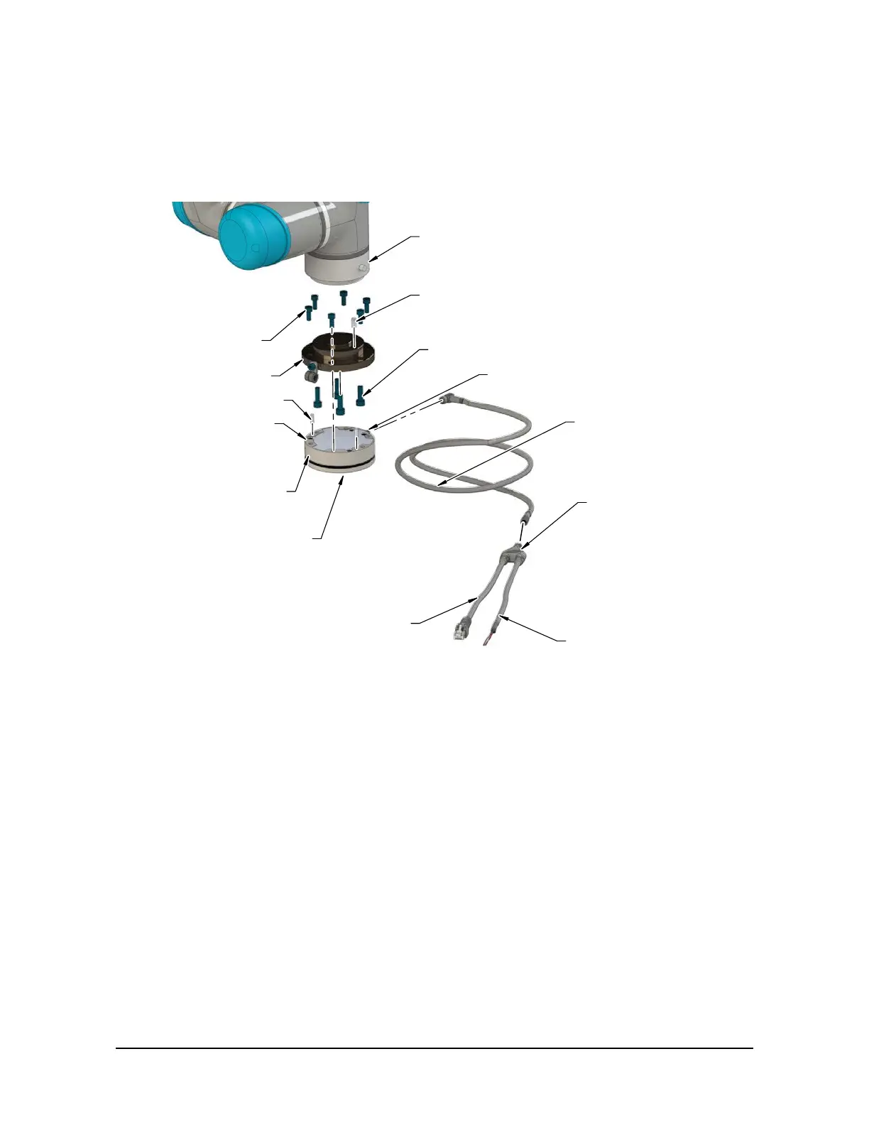
Figure 3.5—Installation of the Sensor to the Robot
Dowel Pin
Mounting Fasteners
Interface Plate
(2) Dowel Pin
Robot
(6) M5 Mounting Fastener
Power and Ethernet Cable
(ATI P/N 9105-C-ZC22-ZC28-4)
Ethernet Axia Sensor
Power and Ethernet Cable to
the customer's application
(ATI P/N 9105-C-ZC28-U-RJ45S-4)
Unterminated End for Power
(Branch 1)
RJ45 Connector
(Branch 2)
Power and Ethernet Connection
Tool Side
for the Customer Tooling
Mounting Side to
the Interface Plate
3.4 Removing the Sensor from the Robot
Tools required: 4 mm hex key
1. Turn off all energized circuits, for example: electrical.
2. Remove the power and Ethernet cable from the sensor’s connection.
3. Supporting the customer tooling and/or interface plate, remove the customer supplied screws that attach
to the customer tooling to the sensor.
4. Supporting the sensor, use a 4 mm hex key to remove the (6) M5 socket head cap screws that secure to
the sensor to the mounting interface plate or robot.
5. Remove the sensor.
 Loading...
