Manual, F/T Sensor, Ethernet Axia
Document #9610-05-Ethernet Axia-09
Pinnacle Park • 1031 Goodworth Drive • Apex, NC 27539 • Tel:+1 919.772.0115 • Fax:+1 919.772.8259 • www.ati-ia.com
24
3.6 Accuracy Check Procedure
Complete the following procedures after the initial installation of the sensor to the robot and once annually
for maintenance.
NOTICE: The mass on the tool side can be the weight of the tooling used in the application.
1. Attach a xed mass to the tool side of the F/T sensor:
a. Remove cables that form bridges between the sensor’s mounting and tool sides.
2. Power on the sensor. Allow a 30 minute warm-up time. Minimize external sources of
temperature change.
3. Move the robot so that the sensor is in the following positions:
a. Record the sensor’s output, F
x, point n
\ F
y, point n
\ F
z, point n
at each point without biasing:
• Point 1: +Z up
• Point 2: +X up
• Point 3: +Y up
• Point 4: -X up
• Point 5: -Y up
• Point 6: -Z up
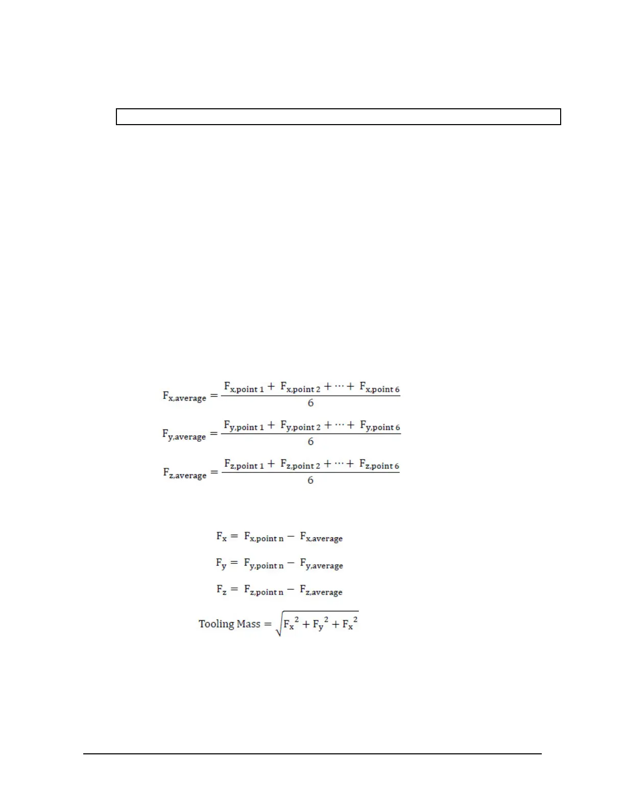
4. Calculate F
x, average
\ F
y, average
\ F
z, average
:
a. Use the following equations, to complete the calculations:
5. For each of the 6 points, complete the following calculation:
 Loading...
