Manual, F/T Sensor, Ethernet Axia
Document #9610-05-Ethernet Axia-09
Pinnacle Park • 1031 Goodworth Drive • Apex, NC 27539 • Tel:+1 919.772.0115 • Fax:+1 919.772.8259 • www.ati-ia.com
23
3.5.3 Pin Assignment for Cable P/N 9105-C-ZC28-U-RJ45S-X
This cable has (2) branches: an unterminated end for power and a RJ45 connection for Ethernet.
For the signals and corresponding pin numbers/wire color, refer to the following sections.
3.5.3.1 Branch 1, Unterminated End for Power Connection
The signals and corresponding wire jacket color for the unterminated wires which
connect to the customer’s device are in the following table:
Table 3.6—Branch 1, Unterminated End: Wire Jacket Color, and Signal
Wire Jacket Color Signal
- Shield
Brown V+
Brown/White V-
Blue/White(TP1+)
1
Sync
Blue(TP1-)
1
Sync Ground
Note:
1. Reserved-not used.
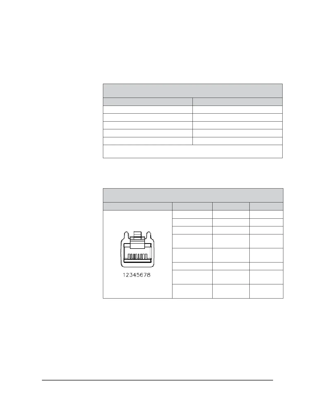
3.5.3.2 Branch 2, RJ45 Connection for Ethernet
The signals and corresponding pin numbers for the 8-pin RJ45 connect which connect
to the customer device are in the following table:
Table 3.7—Cable P/N 9105-C-ZC22-ZC28-X Pin Assignment
for the 8-pin, RJ45 Connector
Connector Schematic Pin Number Wire Color Signal
1 White/Orange TX+
2 Orange TX-
3 White/Green RX+
4 -
No
Connection
5 -
No
Connection
6 Green RX-
7 -
No
Connection
8 -
No
Connection
 Loading...
